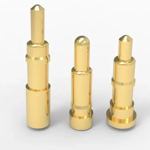
Engineering Resources: Technical Specifications
Electrical Specifications: |
|
|---|---|
| Specification | Value |
| Rated Continuous Current | up to 50A, or even 60A, |
| Peak / Pulse Current | up to 80A, or even 100A, |
| Rated Operating Voltage | up to 550 V, custom 5,500V. |
| Initial Contact Resistance | 10–100 mΩ, |
| Contact Resistance | as low as 10 mΩ, |
| Contact Resistance After Cycling | ≤50 mΩ, |
| Insulation Resistance | ≥1,000 MΩ. |
| Dielectric Withstanding Voltage | 500 VDC test, |
| Temperature Rise | <30°C in 5 minutes, |
| Electrical Continuity | Continuous engagement. |
| Inductance | <0.3nH, |
| Capacitance | <0.2pF, |
| Characteristic Impedance | 50Ω, 50Ω / 100 Ω differential designs, |
| S11 | < 0.5dB, |
| S21 | > -1dB, |
| Crosstalk | < -25 dB, custom 20 dB to -40 dB, |
| Hot-Plug | LMFB or FMLB, |
| ESD | System-level protection. |
Mechanical Specifications: |
|
|---|---|
| Specification | Value |
| Barrel Diameter | Ø1.50 mm. or ≥Ø0.15 mm, |
| Plunger Diameter | Ø0.90 mm. or ≥Ø0.08 mm, |
| Free Length | 5.00 mm. or ≥1.40 mm, |
| Working Height | 4.00 mm. or ≥1.20 mm, |
| Mechanical Stroke | 1.50 mm. or ≥0.10 mm, |
| Recommended Working Stroke | 1.00 mm. |
| Minimum Compression | 0.50 mm. or ≥0.10 mm, |
| Maximum Compression | 1.20 mm. or ≥0.10 mm, |
| Pin Pitch | 2.54 mm. or ≥1.00 mm, |
| Contact Tip Diameter | Ø0.80 mm. or ≥Ø0.08 mm, |
| Contact Tip Geometry | Rounded / Flat / Crown / Conical / Custom, |
| Barrel Wall Thickness | ≥0.15 mm. |
| Plunger Guidance Clearance | ±0.01mm, ±0.007mm, ±0.005mm, |
| Housing Length | ≥3.00 mm, |
| Housing Width | ≥2.00 mm, |
| Housing Height | ≥1.38 mm, |
| Contact Position Accuracy | ±0.05 mm, |
| Pin Height Coplanarity | ≤0.05 mm, |
| Axial Alignment | ±0.1°, |
| Angular Misalignment | 0° or self alignment, |
| Lateral Offset Allowance | 0.10 mm |
| Maximum Side Load | 0 N, or random load based on ball point pogo pin, |
| Retention Force | 5 N per pin, |
| Total Mating Force | 0.8 N x pin count, |
| Total Unmating Force | 0.5 N per pin, |
Spring Force and Motion: |
|
|---|---|
| Specification | Value |
| Initial Contact Force | 0.15 N, or 0.05–0.80 N |
| Force at Working Stroke | 0.80 N at 1.00 mm, or ≥0.05 N |
| Force at Max Compression | ≥0.50 N, |
| Spring Rate | 0.20–1.50 N/mm, |
| Force–Stroke Curve | Linear over working range, |
| Contact Force Variation | ±20%, |
| Spring Preload | 0.05–0.80 N |
| Permanent Set | ≤0.05 mm, |
| Spring Material | SUS631, SUS304, BeCu, SWP-B, |
| Force Attenuation | <5% after 100,000 life cycles, |
| Life Cycles | 10,000–500,000 cycles, |
| Return Height | 5.00 mm free height, custom, |
| Sliding Friction | Dual springs for spring force ≥0.10N at ≥0.1mm, |
| Plunger Sticking | No sticking, |
| Overtravel | Max compression, housing-limited. |
Materials and Surface Finish: |
|
|---|---|
| Specification | Value |
| Plunger Base Material | Brass, BeCu, TeCu, Phosphor Bronze, SUS303/304, SUS316L/F, others, |
| Barrel Base Material | Brass, BeCu, TeCu, SK4, Phosphor Bronze, SUS303/304, SUS316L/F, |
| Spring Material | SWP-B, BeCu, SUS631, SUS304 |
| Pin Plating | Gold over nickel, Au, Ag, Rh, Ru, Pd, Pt, Cu-Sn-Tin, composite plating, |
| Gold Plating Thickness | Up to 5.0 µm, |
| Nickel Underplate Thickness | 1.25–3.00 µm, |
| Plating Hardness | ASTM B 488,130 – 200 HK₂₅ |
| Plating Porosity | 100-300 holes/cm²,or <100 holes/cm², |
| Surface Roughness | <Ra 0.8 µm, |
| Mating Surface Material | Gold-plated PCB pad or target pin, |
| Mating Surface Finish | Gold finish or refer to pin plating above. |
| Housing Material | LCP, PA46, PA9T, PA6T, HTN, PBT, PEEK, PPSU, PEI, PPE, PS, ISO10993 |
| Housing Flammability | UL 94 V-0, |
| Material Conductivity | up to continuous 50A as low as 15 mΩ, |
| Material Hardness | BeCu 400 HV, brass 62-175 HV, Au 200 HV, Pd 650 HV, Rh/Ru 700 HV, |
| Corrosion Resistance | Duration in 5% salt solution: 24h, 48h, 72h, 96h, 120h, |
| RoHS | Yes, RoHS(2015/863/EU) |
| REACH | Yes, REACH, SVHC, |
| Traceability | Material L/C, finish L/C, production D/C, inspection records. |
PCB and Assembly Specifications |
|
|---|---|
| Specification | Value |
| Mounting | SMT, Through-Hole, Right Angle, 90° Bending PTH, Press-Fit, Solder-Cup |
| Pad Diameter | 0.20-0.40 larger than pin tail diameter, |
| Pad Pitch | ≥1.00 mm, |
| PCB Thickness | 1.20–1.30 mm pin length for 1.00mm PCB, 1.80–1.90 mm pin length for 1.60mm PCB, |
| Hole Diameter | 0.20-0.40 larger than pin tail diameter, |
| Hole Position | It’s based on ≥1.00 mm pitch, |
| Soldering Process | SMT reflow, wave soldering 260℃ <7s, manual PTH 340℃ 3s. Standard N52 magnetic connectors avoid reflow and wave soldering. |
| Peak Temperature | 260°C <7s, |
| Reflow Cycle Count | Up to 2 times, |
| Solder Joint Strength | ≥ 5N, Solder climbing height 1/2-3/4 of tail pin, |
| SMT Coplanarity | ≤0.10 mm, |
| Pick-and-Place | 50–100 gf, proposed accuracy ±0.03 mm, |
| Packaging | Tape-and-reel, PE bag Bulk, |
| Pad Flatness | Ra < 0.4 μm, |
Environmental and Reliability Specifications |
|
|---|---|
| Specification | Value |
| Operating Temperature | −40°C to +85°C, custom continuous 350℃, |
| Storage Temperature | −40°C to +85°C, |
| Mechanical Cycle Life | Typical 50,000 cycles. 10,000–500,000 cycles |
| Temperature Cycling | -40°C to +85°C for 5 times, -40°C to +85°C +10%RH~90%RH for 10 times, |
| High-Temperature Storage | +85°C, 96hours, |
| Damp Heat Exposure | +60°C + 90%RH–95%RH, 96hours, |
| Salt Spray Exposure | 5±1% salt, 35±2°C, continuous 48 hours, or 24h, 96h, 120h, |
| Vibration Resistance | 10G, vibration, 10–55–10 Hz/minutes, 1.5mm amplitude at 0.1A. |
| Mechanical Shock | 50G at 0.1A, 11ms, |
| Contact Interruption | ≤1μs @0.5A + >1.15V |
| Wear Resistance | 10,000 cycles, 50,000 cycles, 100,000 cycles based on hard gold plating, |
| Corrosion Performance | Salt spray 48hours, 96hours, 120hours, |
| IP Protection Rating | IP67, IP68 |
| Chemical Resistance | Sweat resistant >168hours, cosmetics resistant to electrolytic corrosion, |
| Dust Contamination Resistance | IP6x reduce dust by >92%, |
| UV Exposure Resistance | 50mΩ based on gold plating and insulation housing, |
| Thermal Aging | 132–228 hours at 105°C, or 168 at 85°C, ≤10 mΩ by LLCR, |
| Reliability Acceptance | Check contact resistance, cosmetic, instantaneous interruption, |
| Qualification Sample Size | 5 or 10pcs samples, |
| Test Report Identification | Model, P/N, testing date, testing standard/method, sample quantity, testing conditions, instrument and equipment information, measured data, judgment conclusion, testing personnel/auditors |
Multi-Pin Connector and Custom |
|
|---|---|
| Specification | Value |
| Number of Contacts | 1, 2, 3 – 4,400pins, custom, |
| Pin Arrangement | Single, Dual, Circular, Matrix, Custom, |
| Power / Signal Integration | Power, GND, Data, Signal (I2C, CAN, RJ45,) Detection, Control, LMFB, FMLB, |
| Pitch | ≥1.00mm, |
| Tolerance | ±0.01 mm, ±0.007 mm, ±0.005 mm, |
| Housing Tolerance | ±0.15 mm, |
| Mating Orientation | Vertical, Horizontal, Angled |
| Polarization / Keying | Magnetic, keyed housing, asymmetric housing, |
| Floating Alignment | Yes, absorb tolerances and misalignment to prevent contact separation, |
| Magnetic Alignment | Yes, >5gf per pin, keyed housing with S/Z-pole, |
| Sealing | IP67/IP68 with Gasket, O-ring, Injection Molding, Overmolding, |
| Mating Force | Spring force per pin x pin count+magnetic force, |
| Retention | ≥300 gf per pin, |
| Shielding / Grounding | EMI, signal integrity with foil shielding or braided shielding, |
| Housing Color / Marking | Black, White, |
| Tip Geometry | Rounded, Flat, Crown, Conical, Concave, Custom |
| Spring | ≥5 gf per pin, |
| 1. Prototype | Verify connector X/Y/Z and angle, minimum/nominal/maximum compression, solder joint quality, plunger movement. And verify contact resistance, continuous current and voltage, magnetic force, and mechanical load. |
| 2. Verification | Johoty verifies contact resistance, voltage drop, temperature rise, and continuity. Johoty guarantees magnetic retention force, separation force, spring force, and retention force. We verify pogo pin connector performance under temperature, humidity, vibration, impact, and dust/water. We finalize the maximum resistance change, allowable force range, and maximum instantaneous break time. |
| 3. Acceptance | Based on AQL, PC-A-610, and ISO9001, we can confirm the accurate size, standard signal pin <30mΩ, and high-frequency/high current <10mΩ. We can guarantee the smoothness of spring force, plunger stroke, and coating uniformity. |
| 4. Change Control | Johoty can follow up on ECOs about pogo pin structure, spring material or force, substrate or coating. And we keep the right magnet or coating, housing, adhesive, wire gauge. We align with clients about PCB surface treatment, mold/fixture/equipment, production location transfer, etc. We can timely cope with notification, approval, and isolation for new and old materials. |