RF Pogo Pin Achieves 10GHz Stability, 0 Loss, 5μm Gold Precision and High Reliability. Ideal For Demanding RF Designs. Offer Best Quote Now!
Introduction: When connection accuracy determines system performance, RF Pogo Pin becomes a key variable
The integrity of high-frequency signals has become a core consideration in Johoty clients’ system designs. The quality of RF connectors is no longer a component issue, but a structural bottleneck in overall performance. High quality RF pogo pin has advantages of high bandwidth, high reliability, miniaturization, and repeatable plugging cycles. Gradually replacing traditional RF connector, it has become the core component of communication, aviation, medical equipment, and even RF testing systems.
Johoty recently conducted a research on the design requirements for ultra 10GHz systems. Among the 21 project leaders from Europe and America, 18 have provided clear feedback. They said traditional SMA, TNC, BNC, and MCX are difficult to meet long-term reliability requirements in applications with frequencies greater than 8GHz. RF pogo pin is one of the ideal alternative solutions.
This article is to show you a systematic analysis of engineering application value of RF connector. Including: structural performance verification at 10GHz and evaluation of zero signal loss. Contact reliability data, cycle life testing, and vibration resistance performance measurement of 5μm gold plating process.
Technical principles and structural composition of RF Pogo Pin
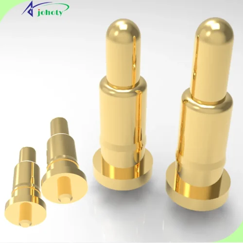
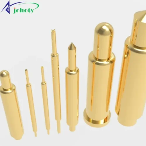
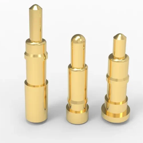
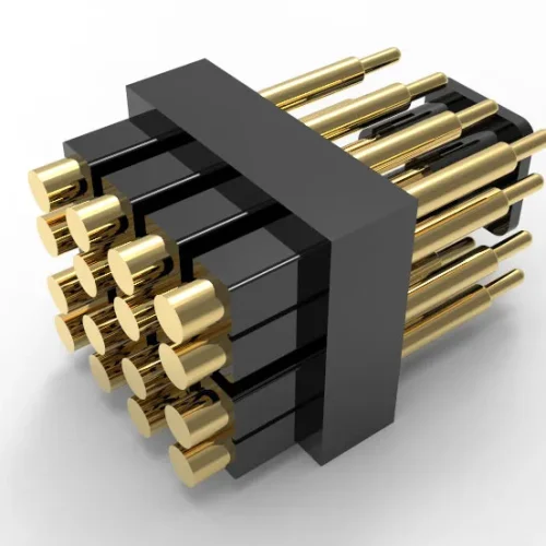
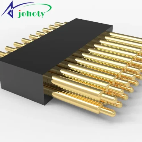
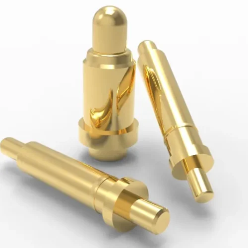
RF connector typically consists of 3 parts: gold-plated plunger, gold-plated barrel, and high-precision gold-plated spring. Unlike traditional rigid RF connectors, it relies on the push contact of the built-in spring on the signal pin. Continuous and stable point-to-point transmission of high-frequency signals.
Electrical characteristics, In the 10GHz frequency range, RF pogo pin must have the following specifications:
- Insertion loss <0.1 dB
- Return Loss >20 dB
- Impedance tolerance ± 5Ω (reference 50Ω)
Johoty assists clients in conducting S-parameter testing in the laboratory using a vector network analyzer. The results show RF pogo pin is at 8GHz and the insertion loss is always controlled within 0.07 dB. The return loss is maintained within the range of 21.5-24 dB. The customer confirms that it can meet the stringent requirements of high-end RF systems.
Johoty’s CNC micro precision process determines RF pogo pin reliability
RF connectors have extremely high requirements for gold finishing. 5μm gold plating has become the recommended standard for RF connector:
- Compared to conventional 0.5-1μm gold plating layers, the lifespan of RF connector can be increased by >10 times.
- The surface contact resistance is stably controlled at 10-15 mΩ.
- Supports over 100,000 cycles of plugging, making it highly advantageous in high-frequency testing.
Johoty uses electroplating + ion beam assisted deposition process to electroplate RF connector under clean room conditions. The gold plating layer is dense and uniform, avoiding particle contamination that may cause stray signals in high-frequency signal.
RF pogo pin often uses a 5μm gold plating process. Aging for 1,000 hours in a 95% RH humid and hot environment results in a contact resistance change rate of <3%. Comparative testing shows that the RF connector has good environmental stability.

Structural Design for Achieving Zero Signal Loss at 10GHz Frequency
The zero signal loss of RF pogo pin is strictly defined as imperceptible loss, not absolute 0 dB. It is an insertion loss below the system noise tolerance threshold, typically <0.1dB in 10GHz applications.
Johoty’s RF connector adopts the following structure:
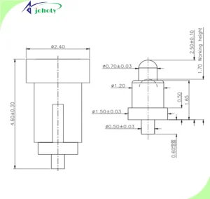
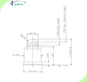
- Short path structure design, pogo pin length<2.0mm.
- Circular coaxial symmetrical conductive channel.
- The central spring is controlled within a deviation range of ± 0.03mm.
Johoty’s RF pogo pin keeps the signal line in a matching impedance channel, avoiding capacitor transients and signal reflections. Through ADS simulation verification, its S21 parameter always remains within -0.06~-0.08 dB. We can fully meet clients’ design requirements of zero loss perception.

Anti-vibration performance verification: from aviation vibration to mechanical impact
For the aerospace environment, Johoty conducted the following tests:
- IEC 60068 Sinusoidal Vibration Test: 10-500Hz, 1.5mm amplitude, 10g acceleration.
- Mechanical impact test: peak acceleration of 50g, half sine wave lasting for 11ms.
- High speed plug and unplug test: 60 times per minute, with 100,000 cycles.
The results show that:
- Throughout the entire testing cycle, there was not a single occurrence of Open Contact.
- Contact resistance fluctuation <0.5mΩ.
- Spring pre-compression deformation rate is <2.8%.
Data verification shows the high stability and lifespan advantages of Johoty’s RF pogo pin in extreme environments. Of course, the main advantage lies in the elastic structure of this spring loaded pin. Commonly used in radar components, satellite communication terminals, unmanned aerial vehicle RF systems, etc.

How to efficiently integrate RF Pogo Pin into customer system design?
Under miniaturization, design engineers generally face the following challenges:
- PCB space is limited, requiring low height RF connectors.
- Interference is prone to occur between multi-channel RF paths.
- High frequency signal integrity testing is difficult.
Johoty’s RF pogo pin has:
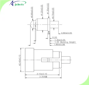
- Minimum height: 1.39mm.
- Maximum center distance accuracy control: ± 0.05mm.
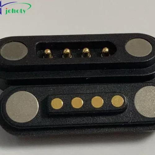
- Support customized shielding covers or grounding structures for practical shielding design.
It can be designed as a pogo pin connector to achieve integrated installation of blind insertion structure. Significantly reduce assembly time and mismatch rate. Customer feedback indicates that this solution performs excellently in 5G PA module validation and RF automatic testing fixtures.

Collaboration data between RF Pogo Pin and aviation radar manufacturers
We have collaborated with a French aviation radar company to develop RF connectors. Johoty’s custom designed RF pogo pin replaces the original SMA+multi-channel PCB adapter solution:
- Reduced assembly space by 35%.
- Increased mating number from original plan of 10,000 to 120,000.
- Reduced insertion loss by 47% in the 9.6GHz frequency band (from 0.13dB to 0.07dB).
Customer stated that the introduction of RF connector has improved system stability, reduced maintenance costs and reliability risks in the later stages. Johoty’s connector has become a standard component for our new generation radar module.
Conclusion: Balancing performance, structure, cost, and delivery
RF pogo pin is no longer test specific or niche connector. It has become an indispensable module component in modern high-frequency design. Commonly used in engineering applications with strong modular structure requirements in frequency bands above 10GHz. It exhibits better comprehensive performance indicators than traditional RF connectors.
Johoty has a deep accumulation in structural design, electroplating process, signal integrity optimization, and testing verification process. We provide hundreds of customized RF pogo pin solutions for high-end manufacturers worldwide. If you are evaluating RF connectors for the next generation of high-frequency systems, don’t miss out on a comprehensive understanding of Johoty’s RF pogo pin.