

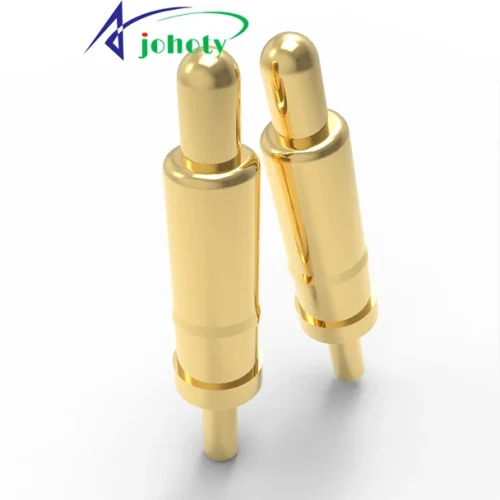
What engineering problems can RF pogo pin solve?
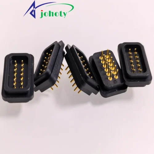
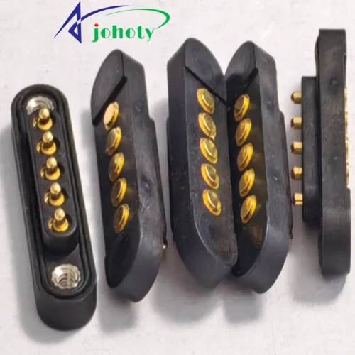
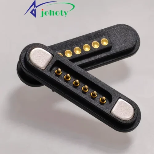
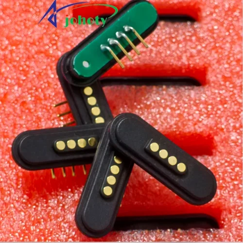
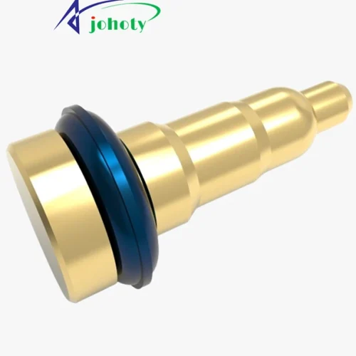
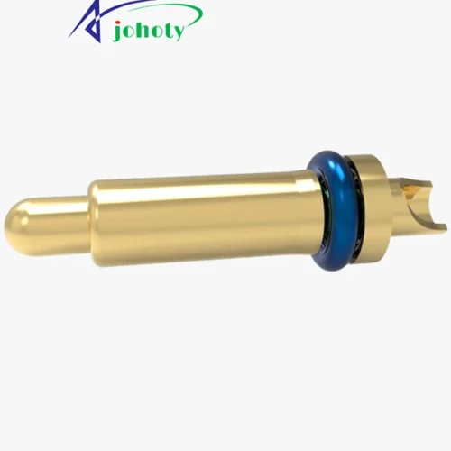
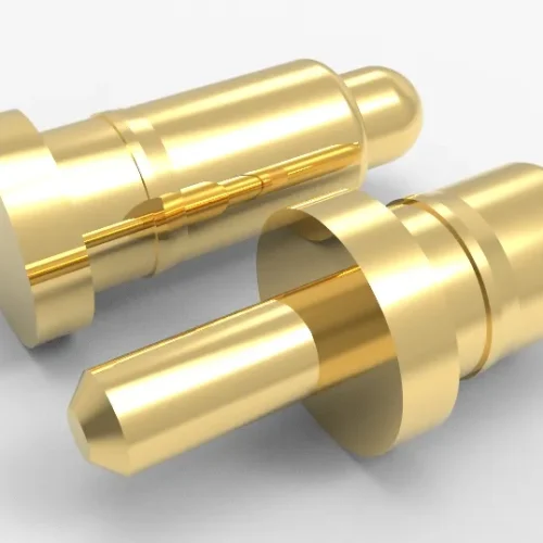
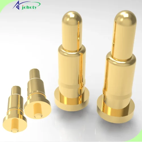
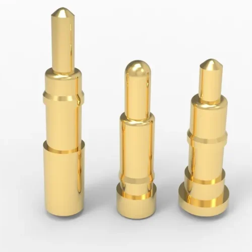
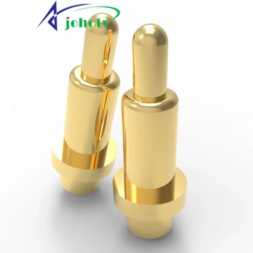
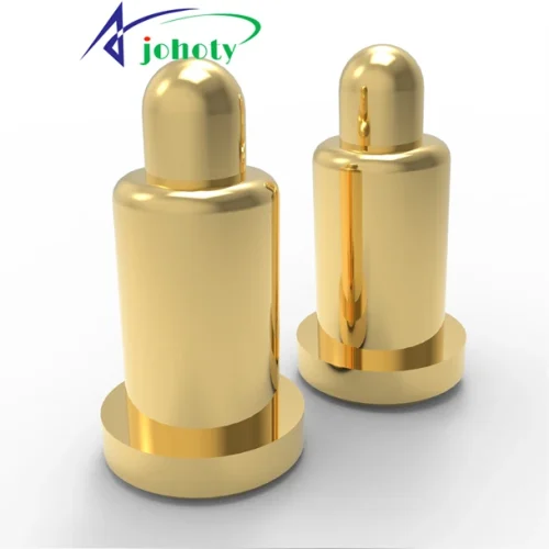
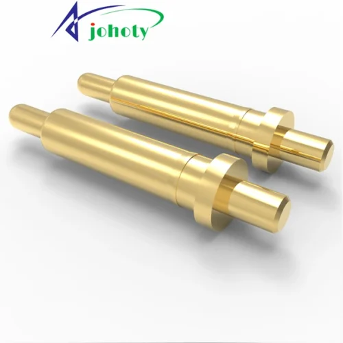
Johoty RF pogo pin is replacing more bulky, difficult to install, and difficult to repair high-frequency interconnect methods. RF pogo pin is designed for board to board and module to motherboard communication, blind mate. Resolve slow assembly, difficult repair, strict alignment, excessively long paths, and unstable contact under vibration. Implement a compressed RF connection solution with shorter paths, easier tolerance absorption, and easier maintenance.
Johoty can shorten RF pogo pin path: The shorter the path, the easier it is to control impedance and reduce insertion loss, reflection, and debugging difficulty. Johoty regards short signal path, controlled impedance, and low noise as the core values of RF pogo pin.
Repeated connection between modules and motherboards: RF pogo pin is a high reliability, multi cycle interconnect. In structures that require frequent maintenance, validation, upgrading, and replacement, it is more in line with engineering reality than one-time welding.
It Can blind mate: RF pogo pin is not just spring loaded pin, but it can absorb assembly tolerances. It can automatically correct X, Y, Z, rotation, and angle misalignment. Johoty RF pogo pin can solve the challenges of module assembly, tolerance stacking, chassis limitations, and on-site maintenance.
Resolve contact instability under vibration and impact: RF pogo pin is more suitable for challenging mating conditions and vibration environments.
Reduce assembly and repair: No soldering, repeatable assembly and disassembly, RF pogo pin is not only faster to assemble. It can also reduce the risk of solder joint inspection, special disassembly tools, PCB damage, and lower TCO.
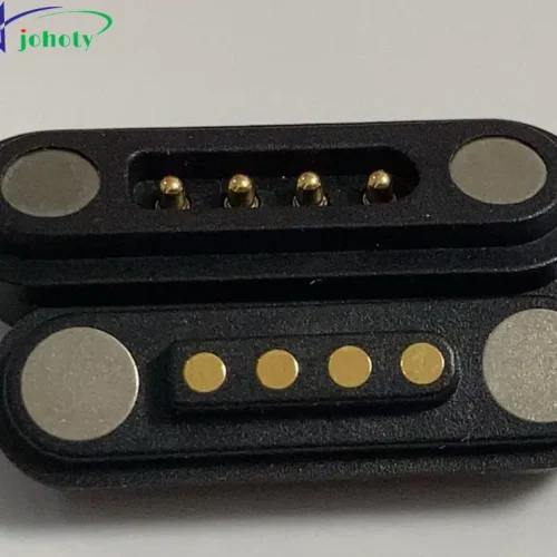
Refactoring board to board RF interconnect: RF pogo pin can integrate COAX, digital, power, and alignment structures together. It can reduce the assembly force during parallel interconnection, simplify the structure, and reduce assembly challenges in complex architectures.
Catelog of RF Pogo Pin?
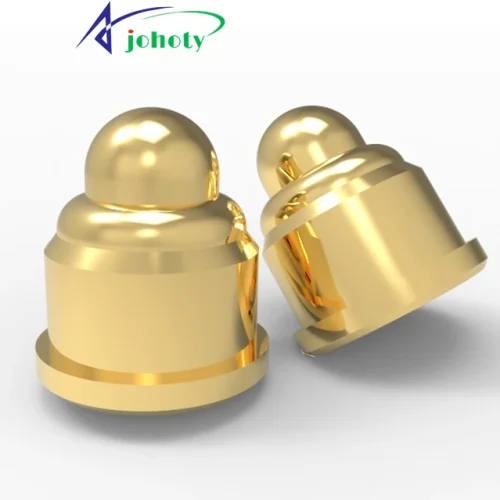
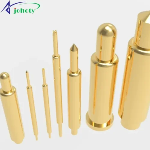
Johoty offers a variety of RF pogo pins designed specifically for high-frequency/speed signal transmission. Suitable for testing fixtures, RF modules, antenna interfaces, and microwave applications. We mainly customize different frequencies and mechanical requirements for you based on the current size structure and appearance. You can customize the RF pogo pin by selecting the appropriate part number from the button below based on your actual application. The installation methods mainly include through hole pogo pins, SMT pogo pins, and right angle pogo pins.
Electrical Performance of RF Pogo Pin?
Nominal impedance: All models are strictly controlled within 50Ω± 1%.
Frequency range: DC-6/7/8/9/10 GHz.
VSWR (Typical/Max): DC-6 GHz:≤1.15~1.20, 6-8 GHz:≤1.20~1.25, 8-10 GHz:≤1.25~1.30.
Insertion Loss: DC-6 GHz:0.10x√f(GHz) dB, 6-8 GHz:0.15x√f(GHz) dB, 8-10 GHz:0.20x√f(GHz) dB.
Return Loss: DC-6 GHz:≥23 dB, 6-8 GHz:≥20 dB, 8-10 GHz:≥18 dB.
Shielding/outer conductor structure: Fully coaxial structure, independent outer conductor signal return path, not dependent on shell grounding. Built in floating structure eliminates air gap discontinuity.
Test conditions:
Test fixture: dedicated high-frequency socket and test PCB,
Calibration plane: End plane calibration,
Cable and adapter: low loss high-frequency coaxial,
Sample quantity: ≥ 5 mate pairs,
Mated pair: Yes, all data is based on pairing testing.
Mechanical Structure of RF Pogo Pin
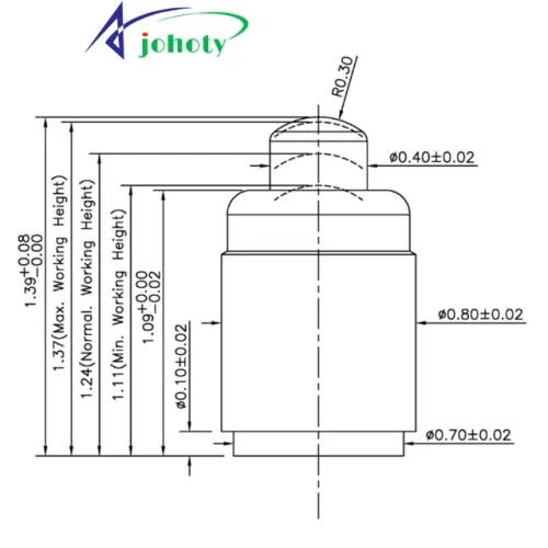
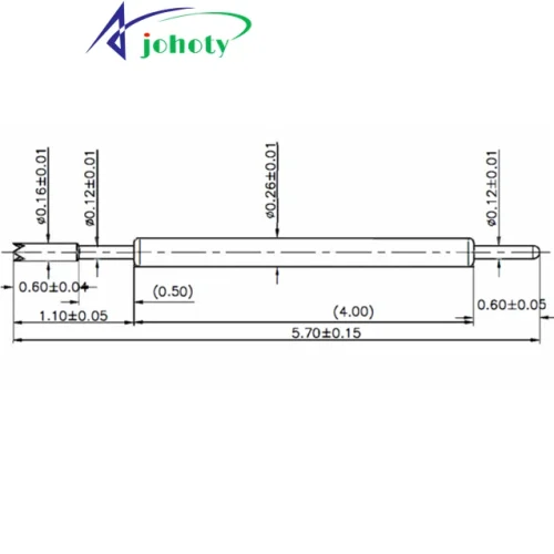
Total length: <6.00mm, different sizes can be selected according to the design to ensure matching PCB and device spacing.
Pre-compression height: Initial height, the height of the plunger tip when not under force.
Work stroke: Reliable contact with the plunger tip compression range to ensure stable signal transmission.
Maximum stroke: The upper limit of overvoltage protection to avoid damaging equipment and RF pogo pins.
Recommended compression ratio: The optimal compression ratio is 60%~70%, ensuring a balance between elasticity and contact pressure.
Spring force curve: Clearly define linear or nonlinear mechanical properties, allowing you to quickly calculate pressure.
Inner and outer conductor structures: display the core signal transmission channel to ensure high-frequency performance.
Head shape: including round, semi-circular, etc., you can quickly determine whether it can be used on the tested terminal or solder pad.
Barrel diameter:0.50mm~5.00mm, Determine if the PCB openings and installation space match.
Installation height: The length of SMT pogo pins, the length of through hole pogo pins excluding tail pins, to assess the risk of mechanical and structural interference.
Installation method: SMT surface mounting, PCB through hole mounting, convenient for process selection.
Floating installation: Yes, allow slight displacement of the plunger tip to adapt to uneven contact surfaces.
Anti-rotation: It will have high stability under assembly and vibration.
Applications of RF Pogo Pin?
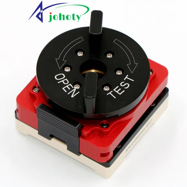
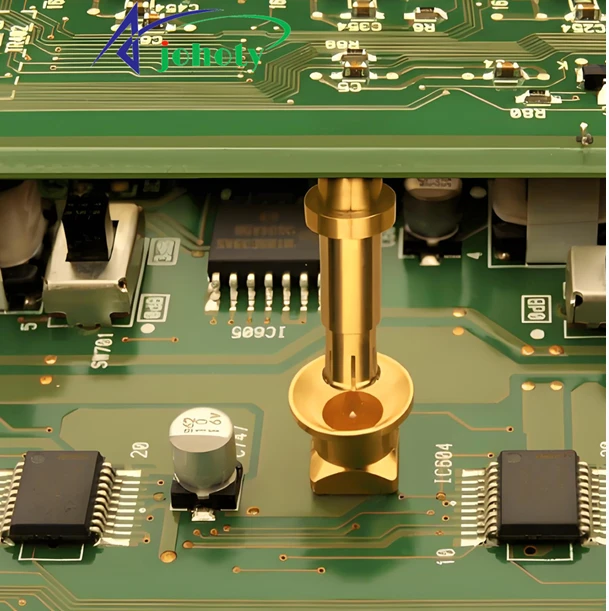
RF test fixture and ATE interface:
Objects: U.FL, MMCX/MCX, miniature coaxial port, module antenna test point, RF switch point.
Why is it suitable? The biggest concern for this type of scenario is the loss of test ports caused by repeated plugging and unplugging, slow board replacement, and poor testing consistency. RF pogo pins are suitable for fast crimping testing. It can be directly integrated into the standard SMA testing link to reduce the deviation caused by manual plugging and unplugging.
Johoty’s suggestions:
Frequency band: DC-6 GHz/DC-12 GHz.
Impedance: 50 Ω.
Structure: Coaxial shielded RF pogo pin.
Head shape: Center guided type/docking with U.FL outer ring positioning type.
Compression capacity: The working compression is about 3.50-4.20 mm.
Outer conductor shielding: It is recommended to have it.
Installation method: flange fixation/thread fixation.
Advantages: High repeatability testing, fast board replacement, consistent testing, and the ability to connect SMA instrument links.
Board to board high-frequency crimping interconnection:
Objects: Removable high-frequency connection between RF daughter board and motherboard. It can’t be soldered dead, but it must be more like a true RF connection than ordinary pogo pins.
Why is it suitable: They require a short signal path, controllable impedance, and easy maintenance. Ordinary pogo pins can conduct, but it is difficult to do a good job in high-frequency links. RF pogo pin designed with coaxial structures is more suitable for short distance high-frequency interconnects.
Johoty’s suggestions:
Frequency band: DC-3 GHz/DC-6 GHz.
Impedance: 50 Ω is preferred.
Structure: Low profile coaxial type.
Head shape: flat head or shallow concave guiding head.
Compression capacity: 0.50-1.50 mm.
Outer conductor shielding: It is recommended.
Installation: It is recommended to have a slight float.
Advantages: Welding free, maintainable, short path, low profile blind mate.
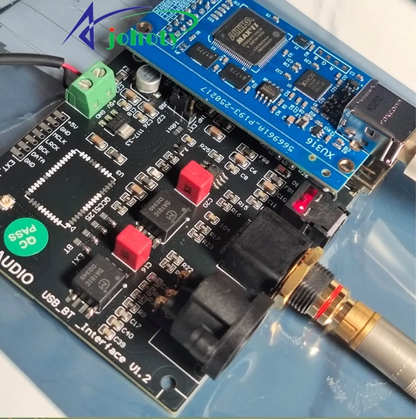
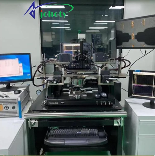
Module and backplane blind mate connection:
Objects: Communication submodule, RF front-end module, backplane pluggable unit.
Why is it suitable? It is impossible to achieve 100% perfect alignment during assembly. The coaxial structure and floating installation of RF pogo pin can maintain contact under certain misalignment conditions. This can reduce maintenance and disassembly costs.
Johoty’s suggestions:
Frequency band: DC-6 GHz.
Impedance: 50 Ω.
Structure: Coaxial contact+floating seat/tolerance compensation structure.
Head shape: dome shaped import type/alignment oriented type.
Compression capacity: 1.00-2.00 mm.
Outer conductor shielding: It is recommended.
Installation: Floating installation is strongly recommended.
Advantages: blind mate, misalignment tolerance, fast assembly, friendly on-site maintenance.
Antenna debugging, calibration, and RF verification:
Objects: Antenna board, wireless module RF front-end、 Develop validation fixtures.
Why is it suitable: Different contact states result in unreliable S parameters and echo data. RF pogo pin isn’t ordinary conductive pin, but is designed for 50 Ω links, repeatable contacts, and S-parameter verification.
Johoty’s suggestions:
Frequency band: DC-6 GHz/up to 12 GHz.
Impedance: 50 Ω.
Structure: Coaxial RF pogo pin with complete outer conductor shielding.
Head shape: Precision centered head shape.
Compression capacity: 1.50-4.00 mm.
Curve: S11/insertion loss curve.
Shielding: There must be an external conductor shielding.
Advantages: Stable repeated contact, verifiable, suitable for research and calibration tooling.


High frequency connection under high vibration and high impact:
Objects: Industrial equipment, vehicle testing, mobile platforms, aerospace and high reliability equipment.
Why is it suitable: What they need is not static conduction, but the inability to break instantly during vibration and drift after impact. This spring loaded pin can be used in harsh environments and has a minimum testing capability of 50G shock and 10G vibration.
Johoty’s suggestion:
Frequency band: DC-3 GHz/DC-6 GHz.
Impedance: 50 Ω.
Structure: High retention coaxial structure and reinforced fixed seat.
Head shape: Dome shaped contact or anti sway guide head.
Compression capacity: 1.50-3.00 mm.
Outer conductor shielding: It is recommended.
Installation: Determine according to the system tolerance, and pay more attention to locking and limiting when there is high vibration.
Advantages: Anti vibration, anti-impact, continuous contact force, long-term repeated connection.
Internal RF interconnection between medical and highly reliable equipment:
Objects: Portable medical equipment, space limited equipment, maintainable internal modules.
Why is it suitable: They value low profile, long-term stability, ease of maintenance, and customizable space.
Johoty’s suggestions:
Frequency band: DC-3 GHz/DC-6 GHz.
Impedance: 50 Ω.
Structure: Low profile customized coaxial RF pogo pin.
Head shape: flat head/slightly concave head/guiding head.
Compression capacity: 0.40-1.20 mm.
Shielding: It is recommended to have an external conductor shielding.
Installation: Depending on the assembly tolerance, floating installation can be selected.
Advantages: Low profile, maintainable, large customization space, long-term stability.
FAQ
Johoty’s concern is not whether it can conduct or not. We pay more attention to whether the signal is still usable, measurable, and reproducible after passing through the connection point.
In RF applications, Johoty controls the impedance continuity, parasitic effect suppression, and contact stability of the contact area. Avoid reflection increase, insertion loss deterioration, or high-frequency response drift caused by spring, end geometry changes, or assembly deviations.
Customers do not only receive a compressible pogo pin connector during actual import. They have received a stable solution for high-frequency testing, antenna connection, RF module docking, and microwave signal transmission. This is crucial, Johoty’s clients, including engineers, doctors, founders, everyone attaches great importance to this. That is: the problem is never whether RF pogo pin is connected, but whether your RF link can still maintain its original design performance.
What really gives engineers a headache is often not passing the test for the first time. But whether the results are still consistent after the 10,000th and 100,000th contact.
Johoty values contact repeatability to avoid test result drift, misjudgment, rework, or system instability. We ensure that stable high frequencies are maintained even after multiple connections, slight positional deviations, overlapping assembly tolerances, and long-term cycles.
Many customers of Johoty have provided feedback that the highest cost is not the parts themselves. Clients hope to avoid:
- After the prototype was adjusted, the mass production results were inconsistent.
- The laboratory test is normal, but the on-site test fluctuates.
- There is a significant deviation in high-frequency performance between different batches.
So, Johoty can turn occasional use into consistent use every time. This is the fundamental difference between standard pogo pin and RF pogo pin.
What we can confirm is that what can be reduced is not procurement risk, but R&D and validation risk.
The real bottleneck for many customers’ projects is not the lack of connector options. But the existing solution will bring about reflection anomalies, unstable testing windows, and prolonged debugging cycles in the system. This directly affects the customer’s judgment of the project. Johoty is more focused on enabling clients to identify and address these risks early on in the project.
For engineers who require rapid validation, this will enable:
- Faster determination of whether the problem comes from the system itself or from the connection interface.
- Reduce repeated testing and misdiagnosis caused by unstable interconnection.
- Shorten the technical confirmation time between sample validation and batch import.
So, many customers contact Johoty not just to find an RF pogo pin replacement. But rather to find an RF pogo pin solution that can enter high-frequency systems and reduce the uncertainty of subsequent engineering.