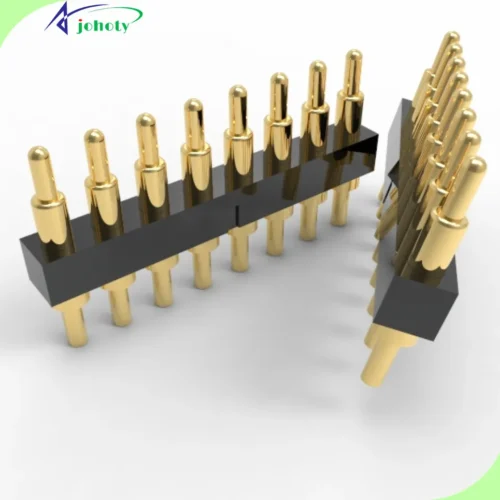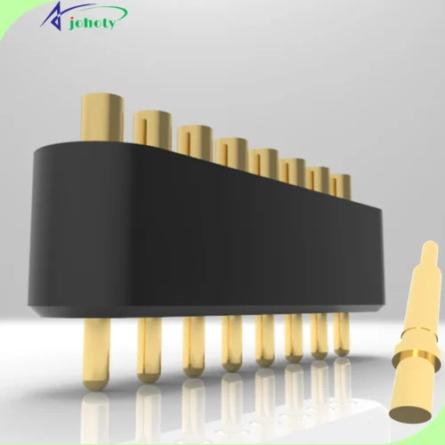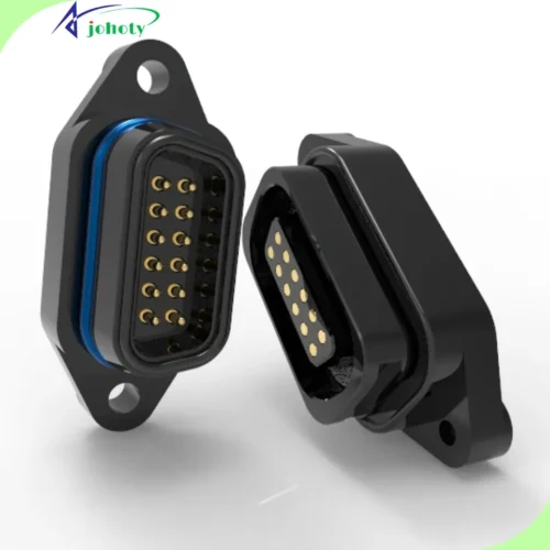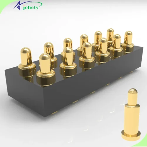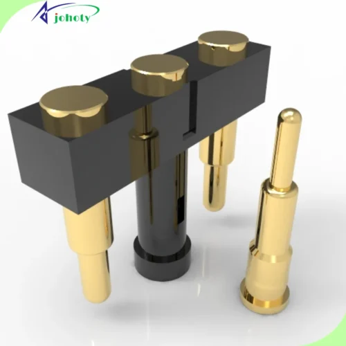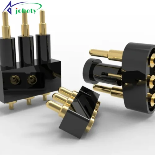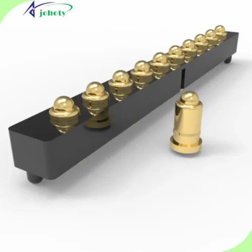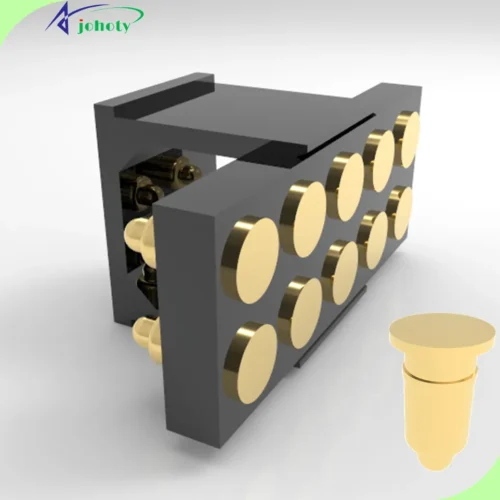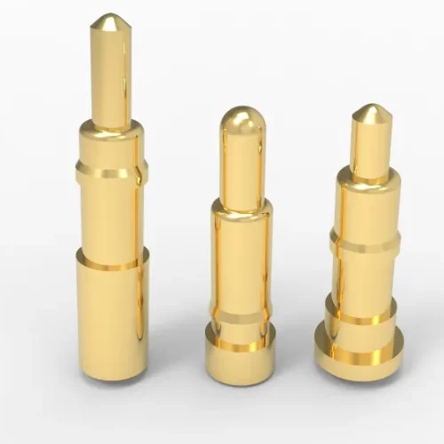


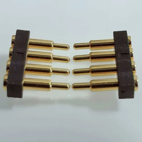
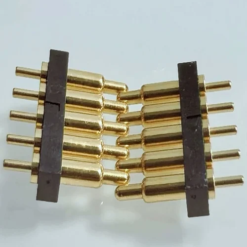
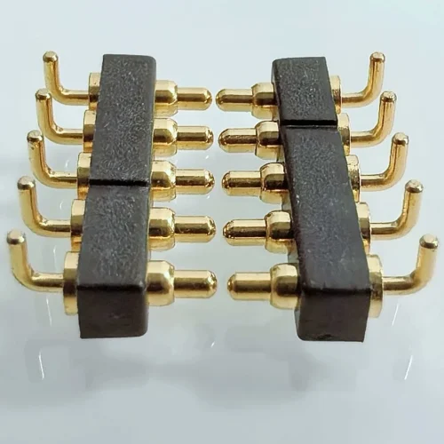
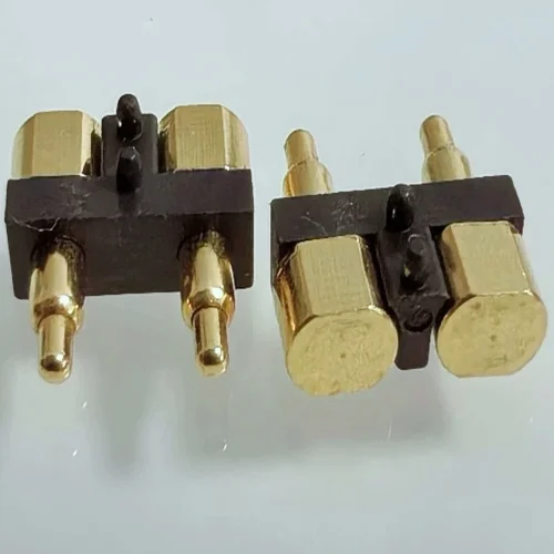
Compliant PCB Connection Works with Your Tolerances
Conventional board-to-board connector depends on two rigid mating halves reaching a narrowly controlled position. When the enclosure or PCB thickness introduces variation, the connector may be exposed to incomplete mating. Also, standoff, mounting screw or assembly process may meet excessive insertion force or mechanical stress.
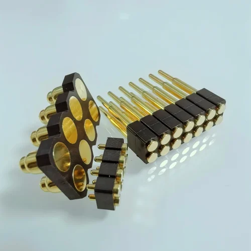
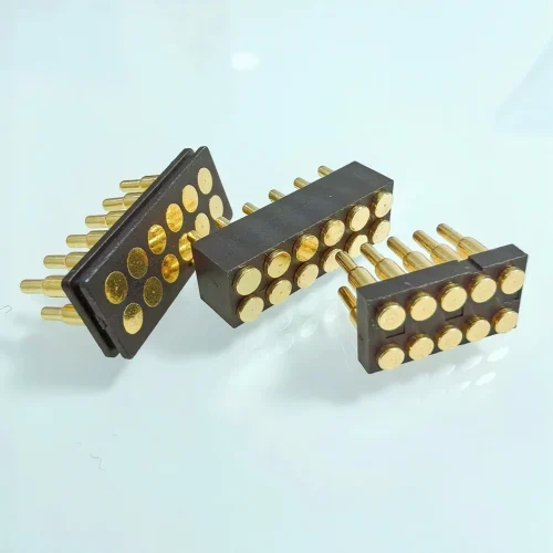
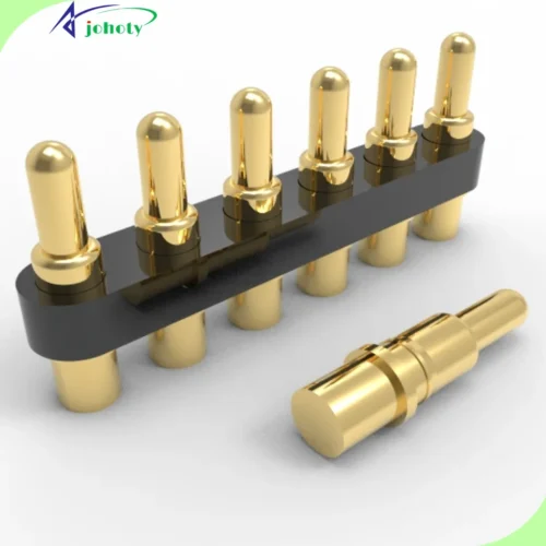
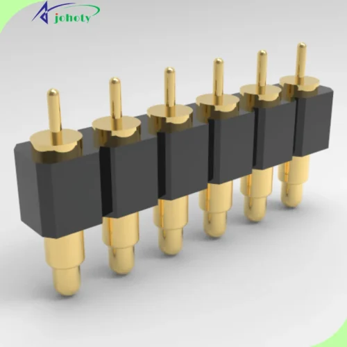
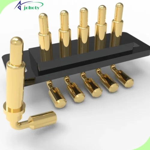
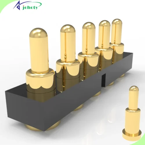
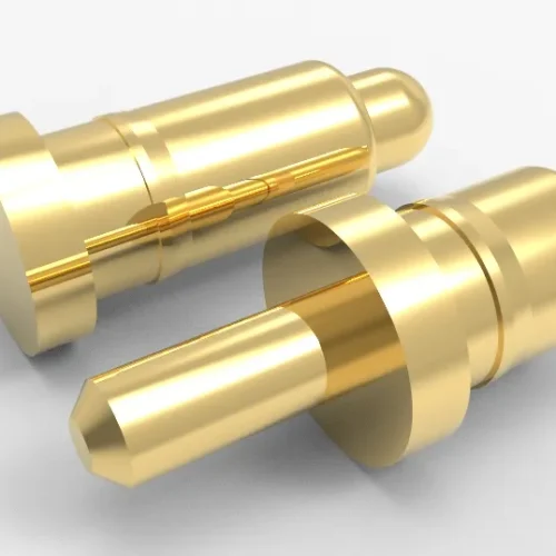
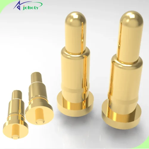
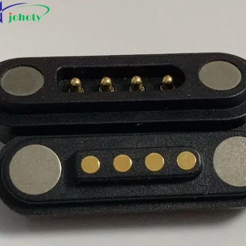
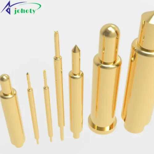
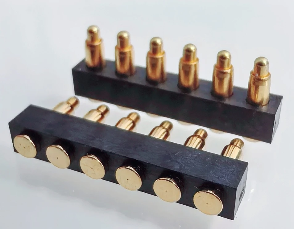
Board-to-board pogo pin connector uses spring loaded pogo pins to maintain force against soldering pad or target area. Working stroke of each pogo pin can absorb part of axial tolerance while maintaining a repeatable electrical path. This is helpful when your design at the following conditions.
Control an uncertain PCB stack height:
Johoty can design free/working height and total stroke based on actual minimum and maximum distance between your PCBs. We select a right working compression from complete tolerance stack instead of a board spacing alone.
Compensate for assembly variation:
Spring travel of board-to-board pogo pin connector can accommodate axial variation. Johoty can manage lateral, angular and rotational misalignment well by guide posts, lead-in chamfers, floating housings and enlarged target areas.
Connect replaceable modules without a fragile socket:
A pogo pin array can connect a replaceable daughterboard, sensor module, battery module or control board. It doesn’t require a conventional male contact to enter a delicate female socket.
Combine power, signal and ground in one board-to-board connector:
Board-to-board connector can use different pin diameters, spring forces, tip and pin assignments in the same housing. Johoty can integrate power contacts, signal contacts, ground contacts and presence-detection contacts into a single board-level interface.
Simplify assembly and field service:
A compression-mated interface can minimize manually inserting or unplugging a conventional connector during production, maintenance or module replacement.
Start with Design Challenge, Not Catalog Part Number
Johoty customizes board-to-board pogo pin connector by electrical, mechanical, environmental, production conditions, because it’ll remain stable in real device.
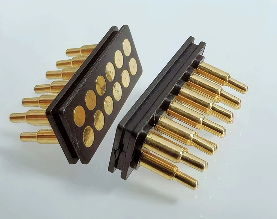
PCB relationship and orientation:
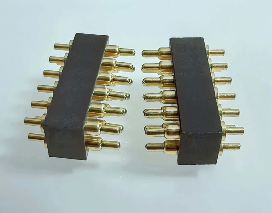
Johoty need to know whether 2 PCBs are parallel, vertical, coplanar, or mounted at an offset. We will evaluate vertical, horizontal, right-angle, and interposer-style accordingly.
Minimum and maximum board spacing:
Johoty always designs board-to-board pogo pin connector around the complete stack-up range. For us, it’s critical sizes for PCB thickness, enclosure dimensions, standoffs, screws. And it’s also important for adhesives, gaskets, warpage and assembly tolerances.
Contact count and pin assignment:
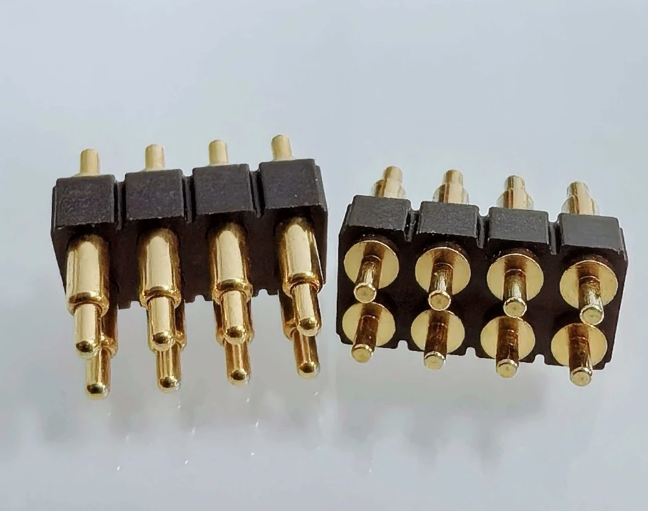
Johoty can provide the required number of power, signal, ground, detection and reserved contacts. A sketch can help Johoty separate high-current paths, sensitive signals and return paths before finalizing the housing.
Electrical load:
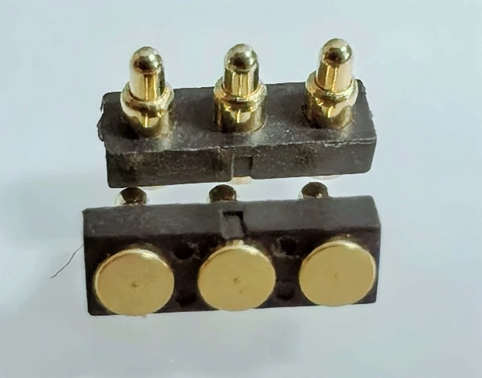
Johoty needs continuous current, peak current, duty cycle, operating voltage in your application. And knowing switching condition, acceptable voltage drop and maximum temperature rise. For a reliable design, current rating is very important.
Signal requirements:
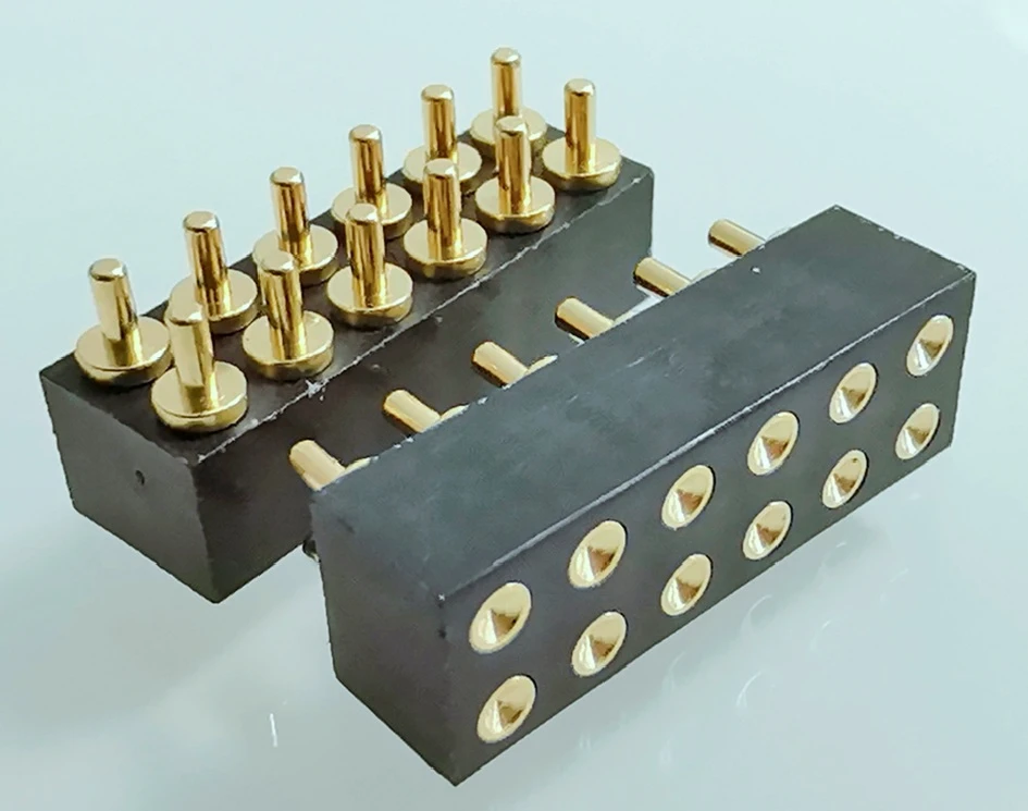
For high-speed or noise-sensitive signals, Johoty needs to know the protocol, data rate, differential impedance. Rise time, allowable insertion loss and crosstalk limits are also the key parameters. Johoty can evaluate differential-pair placement, ground shielding and specialized contact structures then.
Mating frequency:
Johoty needs to know board-to-board pogo pin connector is assembled once, serviced occasionally or mated up to 500k times. We will design plating thickness, tip geometry, target-pad finish, spring force and working stroke based on your life cycles.
Operating environment:
Temperature range, humidity, dust will affect the performance of board-to-board pogo pin connector. Also, it’s also determined by vibration, shock, salt exposure, cleaning chemicals and sealing. A board-to-board pogo pin connector isn’t automatically waterproof. Johoty need to design ingress protection well through the complete housing and sealing.
Production process:
Johoty needs to know you will mount board-to-board pogo pin connector by SMT reflow, through-hole soldering, press-fit installation. Also, it’s helpful to know your selective soldering, insert molding, overmolding or mechanical retention.
Customization of Board-to-Board Pogo Pin Connector
| Parameter | Customization |
|---|---|
| Connection architecture | From pogo pin to soldering pads on PCB, dedicated target, connector interposer, or opposed spring-contact assembly. |
| PCB orientation | Johoty can customize board-to-board pogo pin connector for the contact of parallel, perpendicular, coplanar, vertical, horizontal or right-angle. |
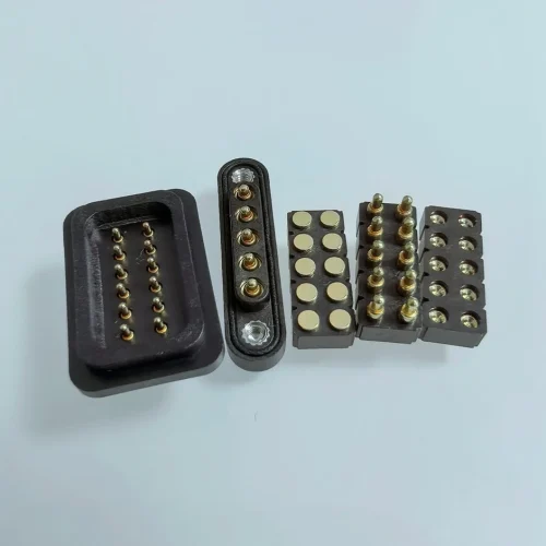
| Contact arrangement | Johoty’s board-to-board pogo pin connector includes single row, double row, multi-row, circular, rectangular, curved or application-specific array. |
| Number of pogo pins | Johoty can design single-contact through high-density multi-contact arrays. We need to review larger arrays according to force, flatness, and PCB support. |
| Pitch | ≥1.00 mm pitch for electrical isolation, housing strength and manufacturing review. |
| Working height | Johoty can offer ≥1.00 mm low-profile and elevated stack configurations. |
| Full stroke | Johoty can design ≥0.10 mm full stroke based on contact diameter, spring structure, and working height. |
| Working stroke | ≥0.10 mm, Johoty can define it at 60%~70% of the force-travel curve after analizing tolerance-stack. |
| Spring force | Johoty can design ≥15 gf per pogo pin according to contact count and system load. |
| Current | Johoty can design signal pogo pin up to continuous 50 A and pass thermal validation. |
| Initial contact resistance | As low as 15 mΩ, Johoty specializes it based on geometry, materials, plating, force and measurement method. |
| Operating voltage | Johoty can customize up to 10KV by pogo pin pitch, housing material, creepage. And based on clearance, contamination level and applicable safety. |
| Signal capability | This includes DC, power, control signals and data. High-speed differential and coaxial structures are available when Johoty reviews signal-integrity. |
| Cycle-life | Johoty can provide 10,000 to 100,000 or more mating cycles for stroke, plating, force and environment. |
| Operating temperature | We can provide around −40°C to +125°C based on the selected materials. |
| Plunger material | Johoty can CNC machine brass, beryllium copper or tellurium copper for conductivity, strength and wear. |
| Barrel material | Precision-machined copper alloy is available for conductivity, dimensional stability and assembly method. |
| Spring material | Johoty can design based on stainless spring steel, SUS631, SWP-B, beryllium copper or application-specific spring alloy. |
| Contact plating | Gold/Ag/Pd/Pt/Rh/Ru over nickel is achieved, Johoty can define plating thickness according to cycle life, corrosion exposure and electrical requirements. |
| Housing material | Johoty can select LCP, PA46, PEEK, HTN for reflow temperature, strength and insulation requirements. |
| Mounting method | Based on our clients’ requirements, Johoty can flexibly design SMT, through-hole, press-fit, right angle, 90° PTH, mechanical retention, insert molding or overmolding. |
| Packaging | Johoty can ensure board-to-board pogo pin connector during delivery by tape and reel, tray, or project-specific protective packaging. |
| Engineering files | We can offer 2D manufacturing drawing, 3D STEP model, pin map and applicable assembly recommendations. |
| Quality documents | We can provide a dimensional inspection report, material information, RoHS/REACH documentation, FAI or PPAP-style documentation. |
How to Ensure Reliability of Board-to-Board Pogo Pin Connector?
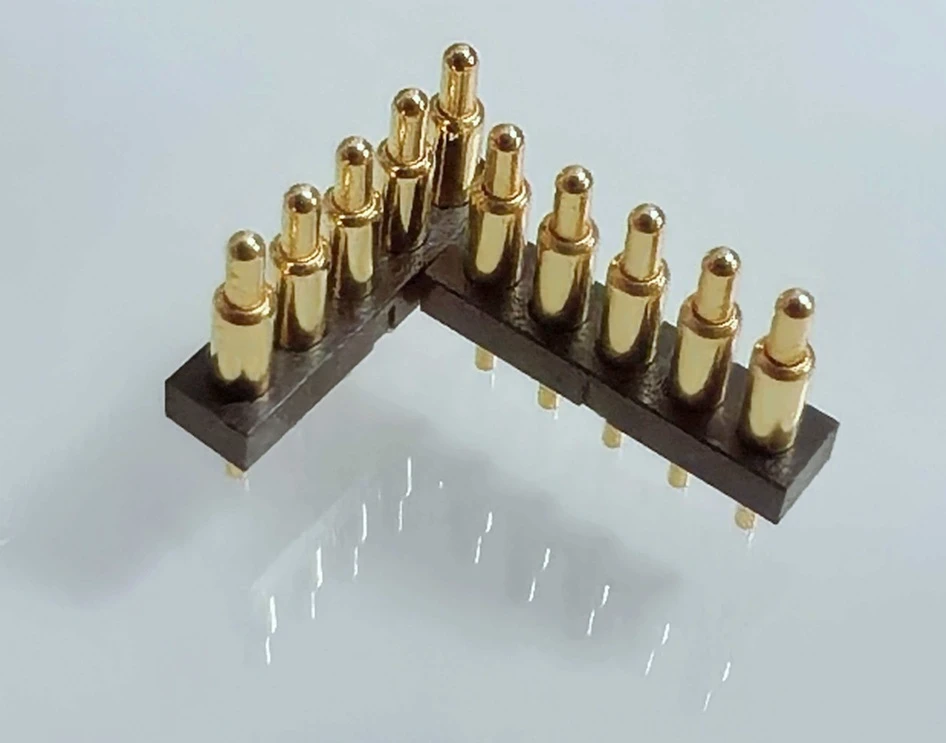
Compression must be designed from the full tolerance stack:
Johoty selects a pogo pin based on its free height fitting the nominal board spacing. We calculates the connector condition at the minimum and maximum possible PCB distance.
At maximum board spacing, the connector must retain enough compression to maintain the required contact force. At minimum board spacing, the plunger must remain safely within its available travel. Johoty needs to ensure not to bottom out or create excessive force on the PCB.
We always review PCB thickness and flatness, enclosure and standoff tolerances, screw or clip position, adhesive and gasket thickness. And housing dimensional tolerance, solder-joint height, thermal expansion, and expected PCB deflection. Johoty review a force-travel curve and the dimensional stack before approving the final working height.
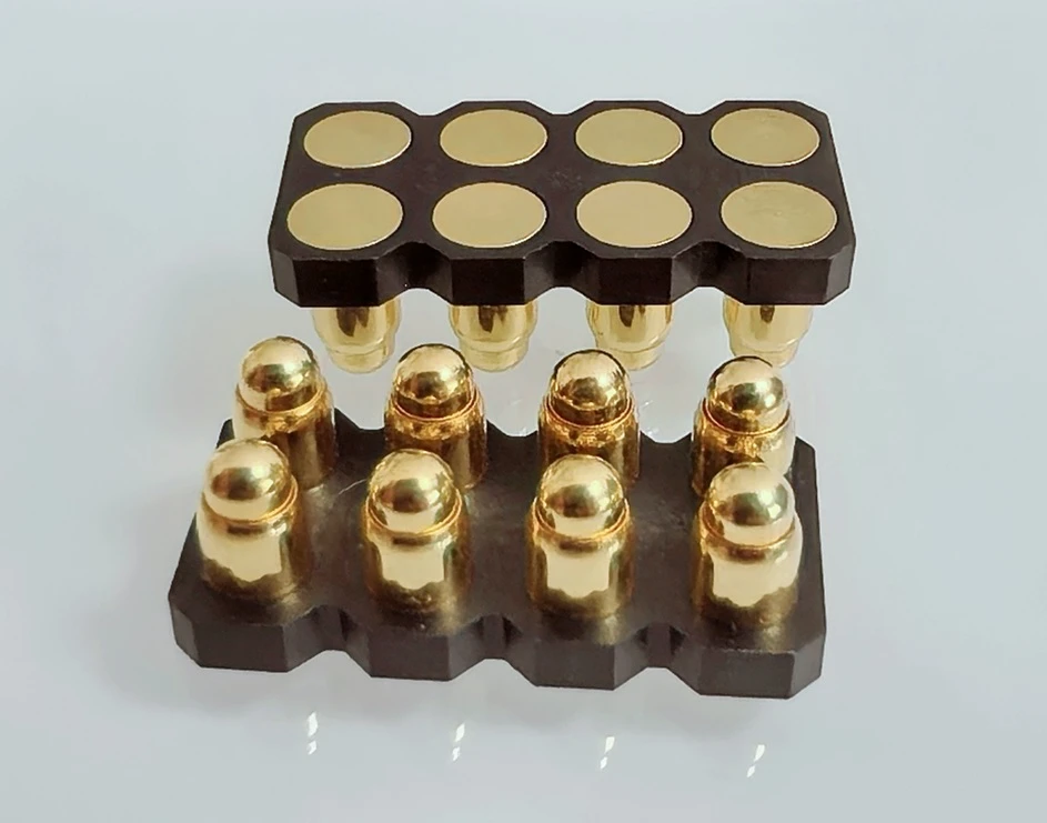
Current is rated by temperature rise, not by diameter alone:
Johoty always clearly states a reliable current specification by the ambient temperature, continuous or intermittent load. It‘s also indispensable for duty cycle, acceptable temperature rise and number of adjacent loaded contacts.
When several power contacts operate together, mutual heating can reduce the safe current of each contact. Johoty can evaluate larger contact diameters and parallel power contacts together. We also look into shorter current paths, lower-resistance materials and dedicated PCB copper areas.
For mixed power-and-signal connectors, Johoty always separates power contacts from sensitive signal contacts. We can also support them by dedicated ground or return contacts.
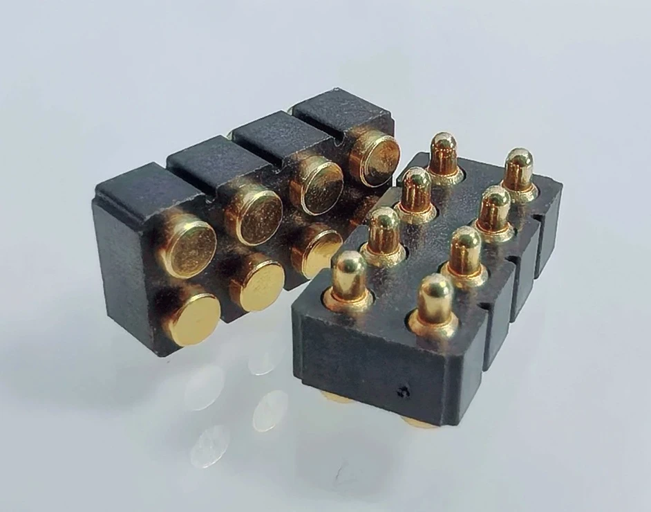
Complete pin field determines high-speed performance:
When placed in an uncontrolled high-speed layout, a pogo pin may be suitable mechanically but not electrically. We always design high-speed board-to-board pogo pin connector carefully:
Johoty follows the procedure of signal-to-ground arrangement, differential-pair symmetry, and contact length. We must pay attention to return-path continuity, pitch and spacing, and housing dielectric properties. We also focus on stub length, crosstalk, and connector-to-PCB transition geometry.
Johoty can design ground-signal-ground arrangements, differential contact patterns or coaxial-style spring contact when clients’ project requires controlled signal integrity.
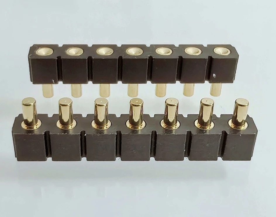
Cycle life and environment with matched plating:
Johoty can define gold plating or composite plating to improve corrosion resistance as well as maintain low contact resistance. An appropriate gold thickness can achieve expected mating cycles, contact force. Also, including wiping action, target finish and contamination level.
When we design a low-cycle internal module, its gold plating is different from frequently serviced industrial interface. Johoty always defines a right plating specification after reviewing the actual usage. We won’t apply one plating thickness to every project.
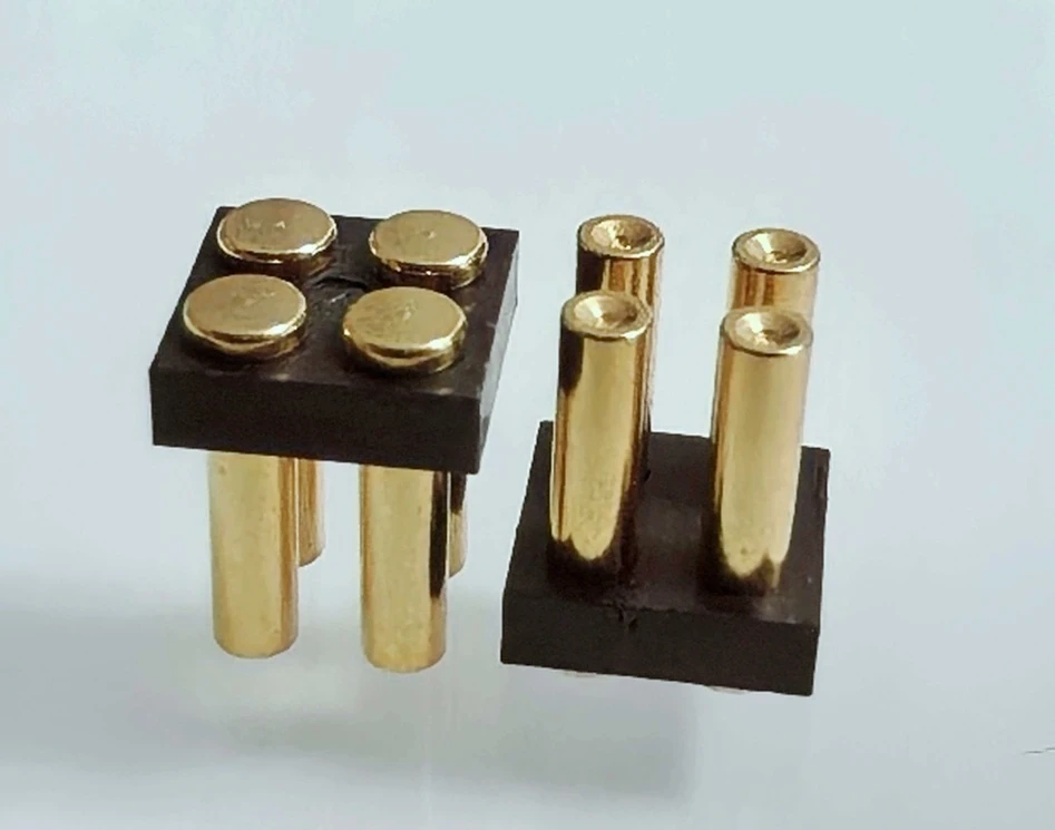
Target pad as part of board-to-board pogo pin connector
Johoty always proposes the opposing PCB pad together with the pogo pin. We can ensure its diameter, shape, surface finish and position tolerance to enhance alignment margin, anti-wear and electrical stability.
For high life cycles, Johoty can offer dedicated target contact for high wear resistance instead of basic PCB pad. For blind-mating, we can also enlarge or combined target area with mechanical guiding features.
Johoty can propose the target pad in the approved connector drawing or application note.
Mechanical misalignment management:
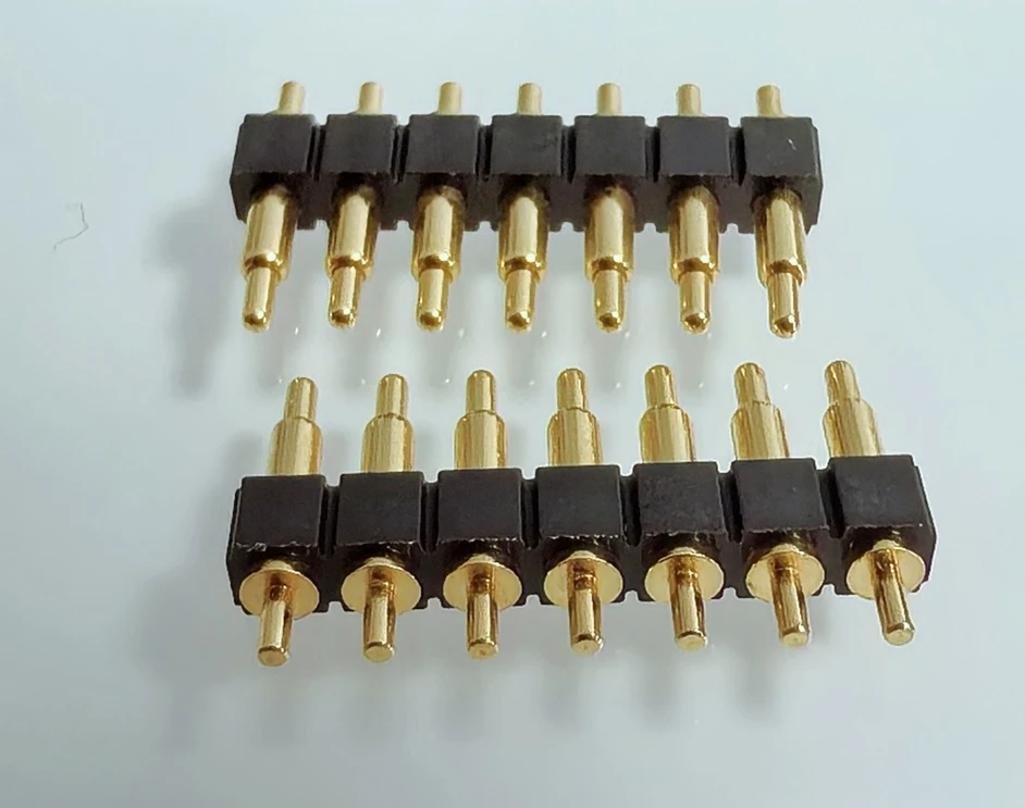
Spring travel primarily compensates for axial variation. However, many clients don’t know this and try to solve unlimited lateral or angular error. If so, Johoty suggestion is to use our ball point pogo pin instead of any types of pogo pins.
Johoty can integratedly design guide posts, guide holes and polarization features. During design, we always think about lead-in chamfers, floating connector plates, and enlarged target pads. Also, we never forget rounded or crown-style contact tips, mechanical stops, and housing features that prevent side loading.
We must ensure guide the PCBs into a controlled mating condition before the contacts are exposed to damaging side force.
Sealing around the complete assembly:
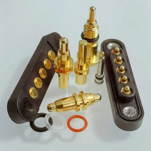
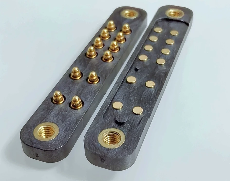
Standard spring loaded pin isn’t inherently waterproof due to its moving plunger. However, sealed board-to-board pogo pin connector requires a housing, gasket, O-ring, injection molding or enclosure interface. It can effectively prevent water and contaminants from reaching the moving contact area.
Johoty can review the required IP level, pressure condition, cleaning method and enclosure geometry before recommending a sealing architecture. In brief, we can design various perfect waterproof board-to-board pogo pin connectors for you.
Total connector force must not overload the PCB:
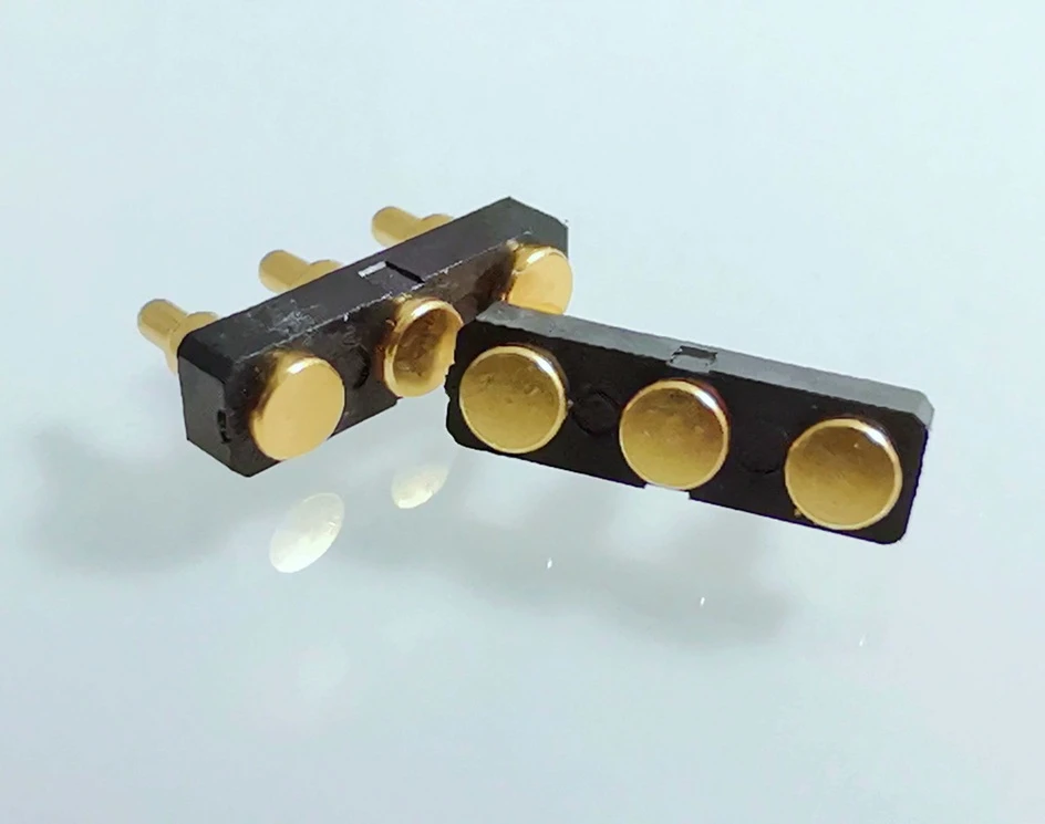
The spring force of one pogo pin may appear low. But, total compression load is the force per pin multiplied by the number of pogo pins.
Obviously, a 60 pin connector array requires a different PCB-support from a 4 pin connector. Johoty can evaluate the total load, mounting-point location, housing support and PCB deflection risk. Sure, we need to finalize the pogo pin count and spring force in advance.
Custom Configurations of Board-to-Board Pogo Pin Connector
Low-profile board-to-board pogo pin connector
For compact wearables, handheld electronics, sensors and slim modules, Johoty can reduce free height, working height and housing thickness. And, Johoty can maintain a controlled compression stroke.
Johoty always studies how to achieve the required stroke, spring force and current within the available Z-height. We won’t reduce height at the expense of reliability.
High-current board-to-board pogo pin connector
Johoty can design power pogo pins by larger diameters, low-resistance. Including specialized internal structures or parallel pin arrangements. We can also integrate signal and sensing pogo pins into the same housing.
Sure, we need to evaluate current density, temperature rise, adjacent-pin heating and PCB copper capacity before confirming the rating.
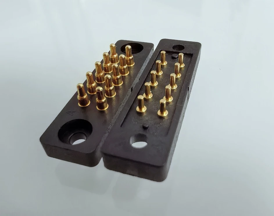
High-density spring-loaded PCB connector
Johoty can provide multi-row pogo pin arrays with a compact interface for modular control boards. And for diagnostic equipment and replaceable electronic assemblies.
We design high-density with careful management of connector flatness and total spring force. And, PCB support, pin-position tolerance, electrical isolation and signal return paths.
Blind-mate board-to-board pogo pin connector
Johoty can design a blind-mate by guide features, lead-in geometry, enlarged targets and controlled float. We need to ensure two modules connect well when operator can’t see the contact interface directly.
We design and ensure 2 connectors mechanical guide engages before pogo pins experience significant compression or side load.
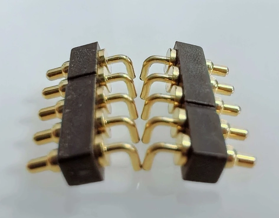
Right-angle board-to-board pogo pin connector
A right-angle spring-loaded connector can link perpendicular or offset PCBs. However, a vertical connector may interfere with the enclosure, display, battery or mechanical structure.
Johoty can review and check SMT, through-hole and mechanically retained right-angle configurations.
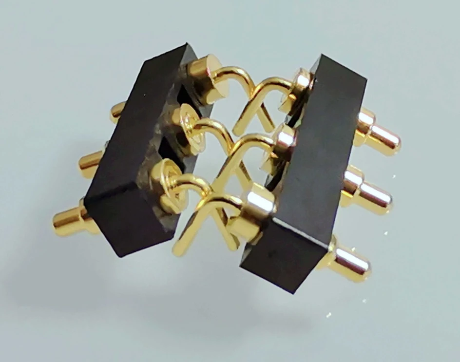
Double-ended pogo pin connector
With reliable housing holding in client’s device, Johoty can design double-ended spring loaded connectors for two target PCBs. Then, you won’t need to permanently solder a conventional connector to both PCBs.
Johoty can support you to simplify module replacement, test access and compression-mounted assemblies by it. For precondition, we need to know a controlled board spacing, parallelism and mechanical retention.
Mixed power-and-signal connector
Johoty can combine different contact sizes and assignments in one housing. We design it to transmit power, ground, communication signals and identification signals.
Johoty can also design first-mate or last-break contact sequencing through controlled pogo pin height. Our segmented connection solution is suitable for an intentional connection order.
Sealed spring-loaded board connector
For outdoor equipment, industrial sensors and exposed modules, Johoty can integrate spring loaded pins into a custom sealed housing.
Johoty needs to review and test the complete connector, gasket, enclosure and assembly method. Then, we can ensure the ingress protection for a sealed spring-loaded board connector.
Validation Plan Before Clients Approving Board-to-Board Pogo Pin Connector
Johoty doesn’t treat a laboratory result from one geometry as a universal rating for every custom connector. We associate each critical performance value with the tested part number, drawing revision and test condition. We can provide our clients with clear, relevant and repeatable test conditions before manufacturing a prototype, sample, mass production.
| Items | What It Confirms? |
|---|---|
| Dimensional inspection | Johoty can ensure in-spec pogo pin position/dimentions/tolerance, housing dimensions, working height, coplanarity and critical tolerances. |
| Force-travel measurement | Spring force is accurate at the defined working compression and available overtravel after Johoty’s spring force & contact resistance tester. |
| Contact resistance | We can guarantee a right or lower contact resistance, for example: 50mΩ, 30mΩ, 20mΩ, etc. |
| Current and temperature-rise test | Electrical and thermal performance is ΔT<30℃ in 5 minutes in the room. Johoty can ensure it meets the specified ambient, duty cycle and contact loading. |
| Voltage-drop test | Johoty can offer the stability of the complete power path under operating load |
| Mating-cycle test | This includes resistance, wear and mechanical performance test, for example: 10k times, 50k times, 100k times. |
| Vibration test | Johoty can guarantee the contact stability under the frequency, acceleration and duration, say, 10G, etc. |
| Mechanical-shock test | It is the resistance to short-duration mechanical impact |
| Temperature cycling | Johoty can design -190℃~350℃ pogo pins and pass the performance test |
| Temperature and humidity test | Johoty can ensure resistance of -55℃~85℃/10%~90%RH to corrosion and insulation degradation |
| Salt-spray or corrosion test | It’s suitable for corrosive environments, seawater, etc, Johoty can design pogo pins with materials and gold or composite plating. |
| Ingress test | Johoty can design IP67/IP68 sealing of board-to-board pogo pin connector. |
| Solderability and reflow evaluation | Johoty can achieve compatibility with the planned SMT or soldering process. |
| Signal-integrity evaluation | Clients can pass the test of impedance, insertion loss, return loss and crosstalk for high-speed signals |
From PCB Layout to Production-Ready Board-to-Board Pogo Pin Connector
1. Before we kick off, what do we need from you?
It’s better for Johoty’s clients to prepare PCB layout, expected mounting, board spacing, and contact drawing in advance. Johoty also need to know current, signal, cycle-life and environmental requirements. Sure, if not, Johoty can co-work on it with our clients.
We will look into the information for missing constraints, conflicting requirements and obvious manufacturability risks.
2. Once we’ve reviewed that, here’s what we can do for you on the concept.
Johoty can propose the connector architecture, pogo pin arrangement, and the working height based on our review. And, we can also propose our client about stroke, spring force, materials and mounting method.
At the stage, our engineering team can accurately evaluate every design details too before beginning our tooling.
3. On the documentation side, here’s what you’ll get from us.
At the moment, We can offer you controlled 2D drawings, which can show you the critical dimensions, materials, plating. In the 2D, we also define spring force, working stroke and electrical requirements for you.
In addition, we can also send you 3D STEP models. Then, your mechanical team can verify enclosure clearance, PCB position, screw location and assembly.
4. What does the prototype phase look like?
We manufacture prototype samples to evaluate dimensional, mechanical and electrical performance.
For standard custom projects, Johoty can complete first samples in two weeks after approving drawing. For high-density, high-frequency, high-current or sealed designs, we can also complete in 2 weeks. Sure, for very complex high-end customization, it’s possible for us to complete in 2~3 weeks even 4~5 weeks.
5. Once you have the first samples, here’s how we handle validation.
We support sample feedback and dimensional correction from our clients. It’s no problem for us to make force adjustments, mating evaluations, and design revisions during engineering and design validation.
We always pre-test and validate critical performance for production materials and processes until our clients approve the whole project.
6. Before we move to mass production, let’s lock down the commercial and quality side.
Before mass production, we can confirm the approved drawing, inspection method, packaging with our clients. At the same time, Johoty’s clients can ask for traceability requirement, quality documentation and change-control process.
In formal quote and invoice, Johoty always clearly states NRE, tooling, MOQ, sample cost and production lead time. Then, our clients can place the order with worry-free.
Where Board-to-Board Pogo Pin Connectors Solve Real Design Problems?
Modular electronic assemblies:
Board-to-board pogo pin connector can connect removable daughterboards, communication modules, sensor boards and control modules. Then, Johoty’s cliet needs to prepare a fragile rigid mating interface.
Medical and diagnostic equipment:
Our board-to-board pogo pin connector can support replaceable modules, charging interfaces, sensor connections and compact internal PCB stacks. All of them require high controlled force and serviceability.
For these devices, Johoty can provide with material, cleaning, biocompatibility or regulatory requirements separately.
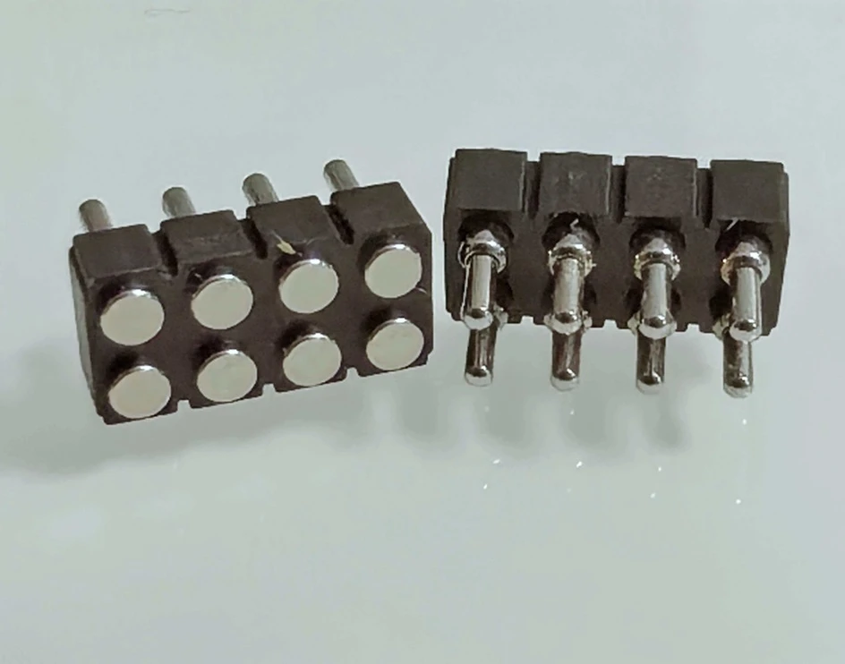
Industrial automation and robotics:
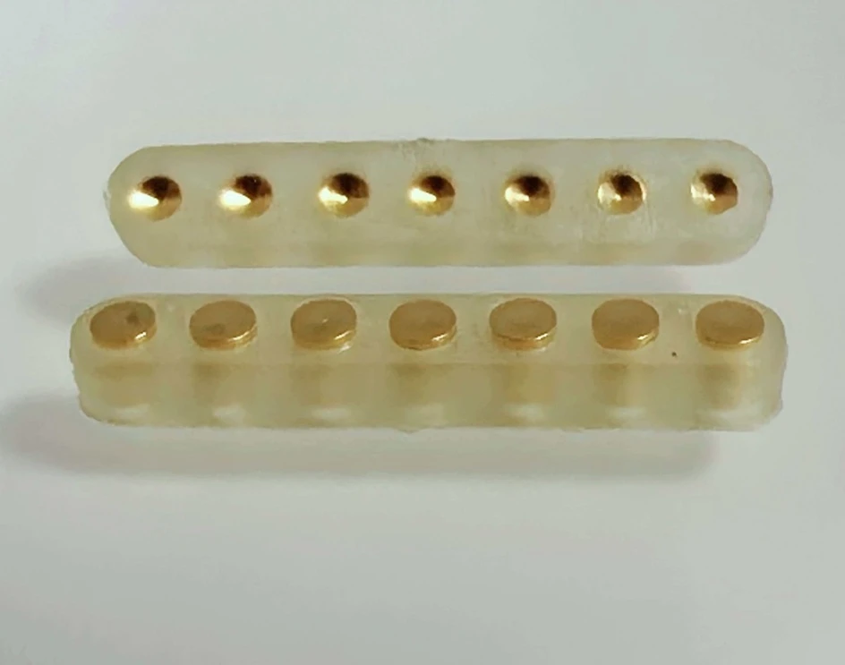
Johoty’s board-to-board pogo pin connector can maintain a compliant connection between control boards and replaceable end-effectors. We can help clients to achieve high stability between sensor modules and serviceable industrial assemblies in vibration or repeated maintenance.
Battery and power modules:
Board-to-board pogo pin connector can combine power, ground, temperature sensing, identification and communication contacts in one custom interface.
Test and measurement equipment:
Johoty board-to-board pogo pin connector can create repeatable connections between replaceable interface boards, instruments, fixtures and devices under test.
Portable and handheld electronics:
We can customize board-to-board pogo pin connector to reduce connector height and simplify module assembly in space-constrained devices.
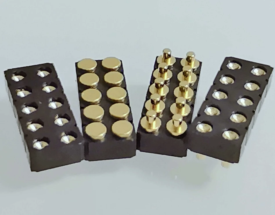
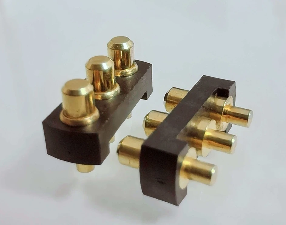
Charging docks and docking stations:
Our board-to-board pogo pin connector can provide a spring-loaded connection that tolerates repeated docking, minor position variation and user-controlled engagement.
Communication and data-acquisition systems:
Johoty board-to-board pogo pin connector integrates power and signal contacts in modular equipment. At the same time, it controls the return path and high-speed layout too.
Why Clients Choose Johoty for Custom Board-to-Board Pogo Pin Connector?
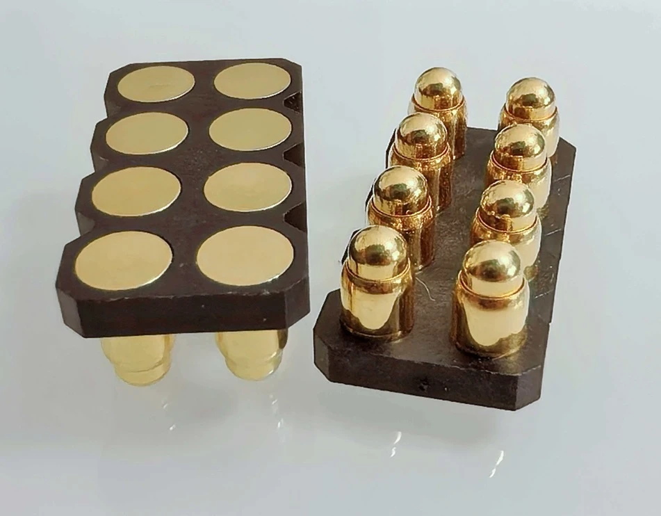
Johoty designs board-to board pogo pin connector around your device:
Firstly, we review the PCB geometry, enclosure, electrical load, mating behavior and production process before finalizing the contact.
Our objective is not to sell the closest existing pin. We always define board-to board pogo pin connector to fit client’s complete system.
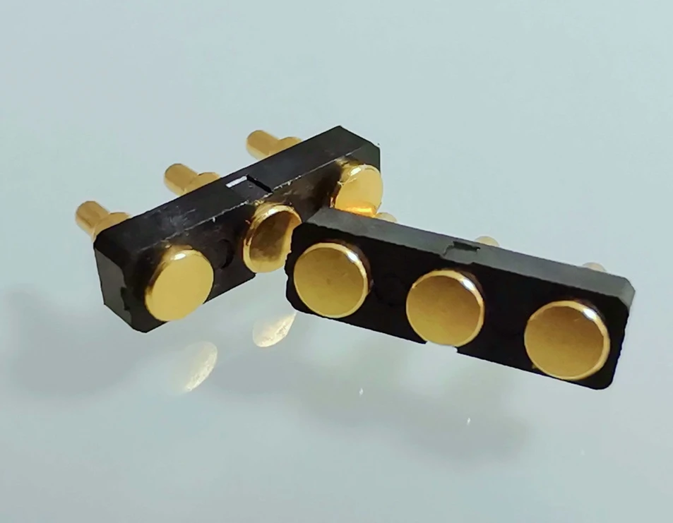
We review mechanical and electrical decisions together:
In board-to board pogo pin connector, stack height, stroke, force, current is easily influence signal integrity, plating and PCB support. Johoty treats all of them as connected design variables rather than independent catalogue fields. This will help our clients to minimize potential risks significantly in their projects.
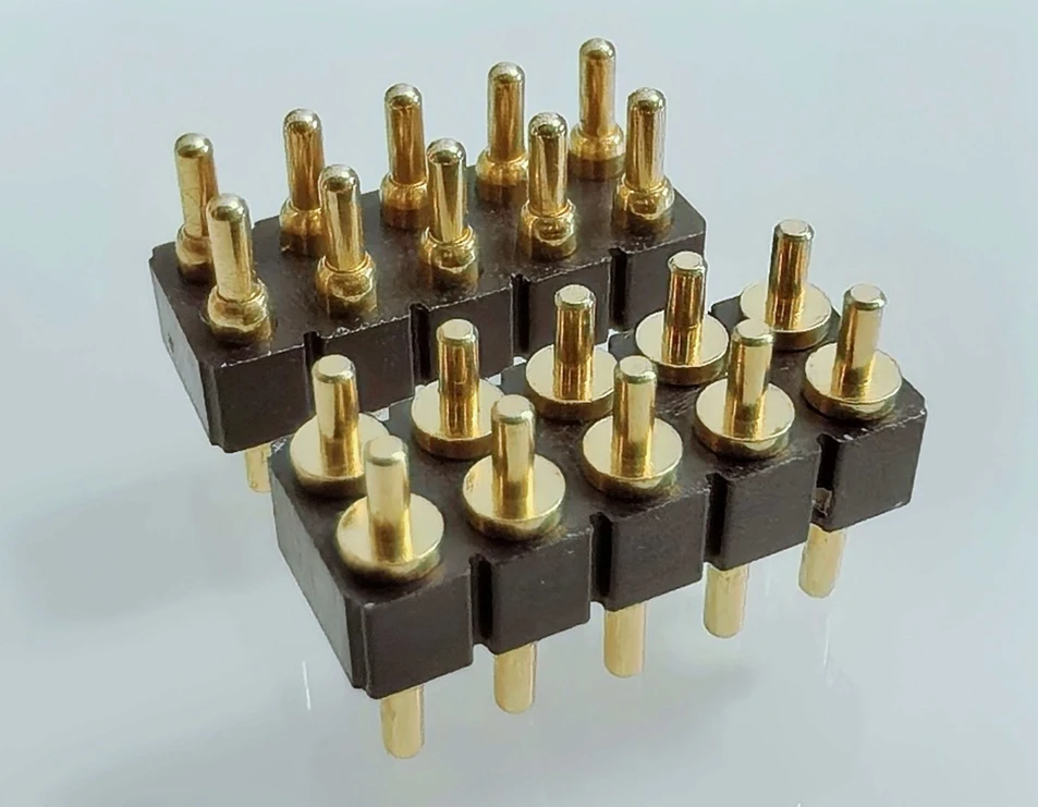
You can receive usable engineering stuff:
We can provide our clients with a controlled 2D drawing, 3D STEP model, pin map for the projects. The stuff also contain target-pad recommendation, sample and validation requirements.
These outputs help our client’s mechanical, electrical, quality and sourcing teams review the same design. This will swiftly align with each requirement from client’s team and avoid any missing or errors.
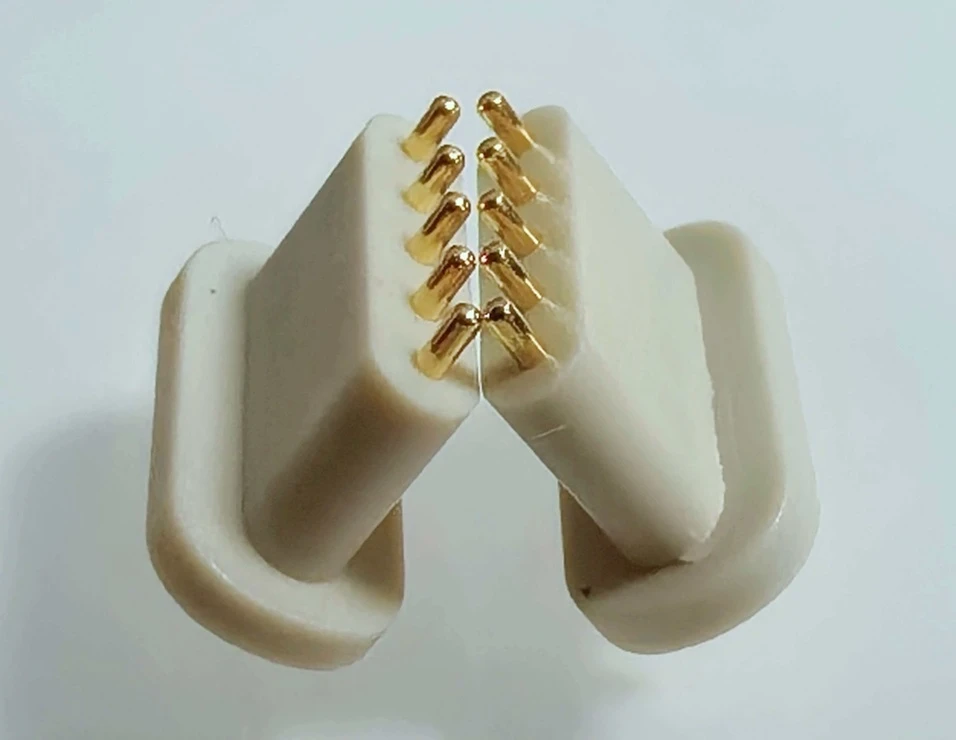
Johoty always states performance boundaries clearly:
We always describe temperature conditions for rated current and compression conditions for a cycle-life. We clearly state the injection molding for sealed housing and IP67 or IP68 waterproof.
In datasheet or drawing, Johoty can states critical specifications for your approval. As for test method, we can also share with our client, including test instruments.
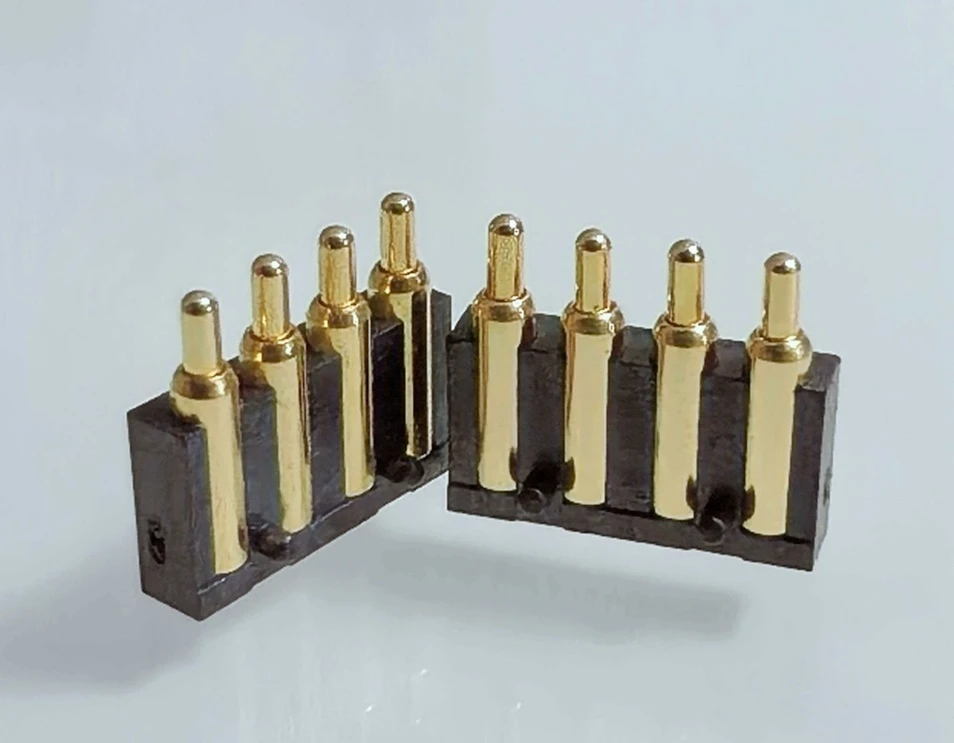
We can support from prototype to production:
Johoty supports custom board-to board pogo pin connector from initial DFM and engineering samples through EVT/DVT/PVT and repeated production. For the standard or high-end custom from OEM/ODM or laboratory, we can offer perfect solutions and mass production. Each batch of board-to board pogo pin connectors, we can guarantee high consistency based on high performance.
Johoty can provide documents for client’s project:
We can provide our clients with various documents. Including material information, RoHS/REACH declarations, dimensional reports, inspection records and customer-specific quality documents. Also, we can prepare spring force test, contact resistance test, gold plating thickness test, and life cycle test reports. Johoty CFT team will closely work with our clients for any necessary.
Have a PCB Stack-Up or Connector Reliability Challenge?
Send Johoty the real constraints before changing your PCB or enclosure around an unsuitable catalogue connector. Our engineering review is most effective when you provide:
Johoty needs to know minimum and maximum PCB spacing and PCB orientation and available connector area.
Pin count and preliminary pin drawings are the basic, including continuous and peak current, signal type or data rate.
We require the mating cycles, temperature and environmental conditions.
Your preferred mounting and assembly process can determine pogo pin shape, estimated prototype and production quantity.
STEP, DWG, DXF, Gerber or PDF files will be greatly for us to work out perfect solutions swiftly and accurately
FAQs of Board-to-Board Pogo Pin Connector
What information does Johoty need to design a custom board-to-board pogo pin connector?
Johoty needs your PCB orientation, available connector area, minimum and maximum board spacing. It’s important for us to know contact count, pin assignment, continuous and peak current. Also critical for signal type, required mating cycles, operating environment and assembly process as well.
Your STEP model, PCB drawing or marked PDF allows us to identify mechanical conflicts and tolerance risks earlier. When complete information isn’t yet available, Johoty can provide a design-input checklist to help your team define the missing requirements.
How should I choose the working height and stroke?
Johoty designs working height based on the full minimum-to-maximum PCB spacing rather than the nominal distance alone.
We need to keep pogo pin retain adequate compression at the largest spacing. Also, we must guarantee sufficient overtravel at the smallest spacing. Before Johoty finalizes the free height, working height and stroke, we need to study many specs and parameters. This includes PCB thickness, housing tolerance, standoffs, and screws. Also, we double check solder height, gaskets, warpage and thermal expansion.
What compression should a board-to-board pogo pin use?
Johoty defines correct compression depends on the force-travel curve and the tolerance stack. In our designs, we place the working point within the 60%~70% of the available travel. We don’t place it near the uncompressed or bottomed-out position.
We design the final compression for adequate minimum contact force without producing excessive total load on the PCB.
Can a pogo pin connector compensate for PCB misalignment?
In board-to-board pogo pin connector, spring travel mainly compensates for axial or Z-direction variation. It is only a standard pogo pin connector, you should control the lateral, angular and rotational errors. Because they are related to guide posts, lead-in chamfers, enlarged target pads, floating housings or other mechanical alignment. For example, the lateral force, perfect solution should be ball point pogo pins instead of standard pogo pins.
Johoty can evaluate a misalignment-tolerant board-to-board pogo pin connector. In usual, we define the allowable offset in the approved design rather than assumed.
Can Johoty combine power, signal and ground contacts in one pogo pin connector?
Yes. Johoty can flexibly design power-and-signal connector by different pogo pin diameters, spring forces, positions and assignments in one housing.
We can effectively separate power contacts from sensitive signals. We can also provide appropriate ground returns and use multiple contacts in parallel. For temperature rise, voltage drop, crosstalk and total compression force, we can finalize the final layout.
How much current can Johoty board-to-board pogo pin connector carry?
Johoty can define the current based on contact diameter, internal structure, materials, and working stroke. We also refer to contact resistance, ambient temperature, duty cycle, PCB copper and adjacent pogo pin quantity.
Yes, we can design high current up to continuous 50A per pin. But we advise confirming the final rating through a defined temperature-rise and voltage-drop test. Johoty can achieve higher total current through specialized contacts or parallel power pogo pins.
Can Johoty pogo pins handle high-speed signals?
Yes, we can design high speed pogo pins and high speed pogo pin connector. However, Johoty hints we shouldn’t treat a standard pogo pin layout automatically as a controlled high-speed interconnect.
High speed pogo pin connector requires low contact resistance, low profile, even coaxial pogo pins. For us, Johoty need to design its layout carefully based on the protocol, data rate, and nearby ground contacts. According to many validations from clients’ project, we can design <12Gbps high-speed board-to-board pogo pin connector.
How many mating cycles can the board-to-board pogo pin connector achieve?
Cycle life is influenced by working stroke, contact force, plunger tip, plating thickness. At the same time, target-pad finish, contamination, alignment and cleaning method can also impact to it.
Johoty can customize up to 500,000 mating cycles if it’s possible to get the right dimensions, materials, and pricing enough. For your specified cycle life, we should verify it by the approved connector, target surface and working compression.
What contact materials and plating are available?
We design contact components based on brass, beryllium copper or other copper alloys, with gold over nickel plating. Springs are often made of stainless spring steel or SUS631, music wire SWP-B, beryllium copper or another spring alloy.
Johoty selects the material and plating thickness according to clients’ required conductivity and spring force. As well as wear, corrosion exposure, cycle life and cost. We state the final material and plating specification in the approved drawing. We always get a alignment with our clients on the finalized materials and gold plating thickness.
Are SMT, through-hole and right-angle available in board-to-board pogo pin connector?
Yes. The 3 types are the pupular board-to-board pogo pin connector. Johoty can evaluate SMT board-to-board pogo pin connectors, through-hole connectors, right-angle connectors. Also, we can offer press-fit contacts, double-ended contacts and mechanically retained assemblies.
We always select the mounting method according to your PCB space, reflow temperature. And, we think about mechanical load, serviceability and production process.
Can a board-to-board pogo pin connector be IP67, IP68 waterproof?
Certainly. Johoty can make IP67, IP68 waterproof. However, we should not assume the spring loaded pogo pin to be waterproof. Because we design a waterproof or dust-resistant based on a complete sealing system around the connector. That is, it needs special inner structure and goes through the process of injection molding.
Johoty can design a sealed housing by gaskets, O-rings, overmolding/injection molding, enclosure-level seals. We test the final IP performance on the completely assembled product underwater.
How long does a custom board-to-board pogo pin connector project take?
Johoty customizes board-to-board pogo pin connector with CNC housing in 2 weeks. And custom housing or injection molding in 4 weeks. So, the lead time depends on the pin number, pitch, and housing materials. And, the lead time will be longer, If you have high housing complexity, electrical requirements and validation scope.
For many custom designs, Johoty can target first engineering samples in two weeks after approving the drawing. For high-density, high-speed, high-current, and small or sealing, we hope to get additional engineering and manufacturing time.
A project schedule for board-to-board pogo pin connector, we should identify the DFM review, drawing approval, prototype. EVT/DVT validation, design revision and production-release are our considerations.