

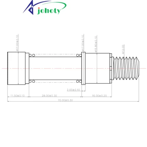
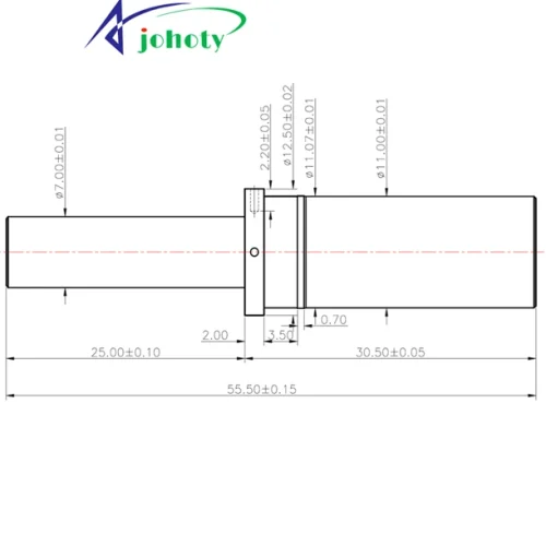
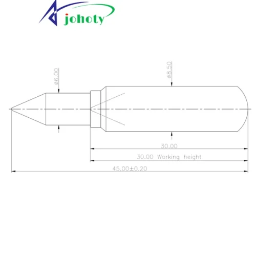

8 challenges for large pogo pins
How big should the installation hole be? If the tolerance is tightened, it can’t be installed, and if it is loosened, it will shake. If the positioning is slightly off center under large dimensions, a set of molds will be scrapped.
How much work compression should be set to be stable? Shallow pressure leads to unstable contact, deep pressure causes barrel deformation. And even a slight deviation of large-sized spring stroke can cause complete collapse.
What is the contact resistance and will it drift in the long term? The initial impedance looks good, it starts to jump and can’t be locked at all after running for many hours.
How much force to press down? Can the assembly withstand it? If the force is too low, it won’t work. If the force is too high, the barrel will crack and the assembly line pressing equipment will directly alarm.
How many amperes can be carried under high current? Nominal value runs smoothly in the laboratory, but the chain falls off when temperature rises inside whole machine.
Will it fail, break, or get stuck under vibration, impact, or biased load? Large pogo pins are most afraid of lateral forces. As they may get stuck or the plunger break with a slight load deviation, causing entire machine to shut down.
How much does it heat up after being powered on? Will it burn housing or affect the surrounding components? Uncontrolled temperature rise, softening of housing, performance drift of adjacent components, and thermal management collapse of the entire machine.
How many times can large pogo pins be used? Is the lifespan based on laboratory data or actual operating conditions? The lifespan measured under ideal conditions is completely different from the actual assembly tolerance and usage environment. And the clients have no idea at all.
Catalog for large pogo pins
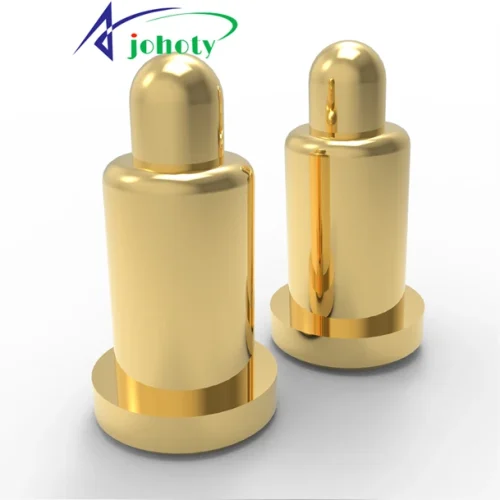
High Current Large Pogo Pins
Installation hole tolerance: ±0.02mm, rigid positioning, to prevent shaking. Johoty can also achieve forward sliding of the needle and <±3° deviation of the plunger.
Compression stroke: 2.50mm~8.00mm, with a stable elastic curve. We can ensure zero micro breakage of contact for the plunger under high pressure.
Contact force: Johoty large pogo pins can reach 25N and maintain a conductivity of 3mΩ even under vibration.
Rated current: Continuous 30A~1,200A, ΔT≤25°C @ rated current.
Contact resistance: 5mΩ, no heating or welding under high current.
Durability: Resistance change rate <5% after 10,000 insertions and removals, vibration test 10G without instantaneous interruption.
Heavy-Duty Large Pogo Pins
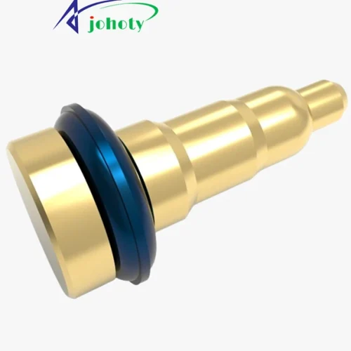
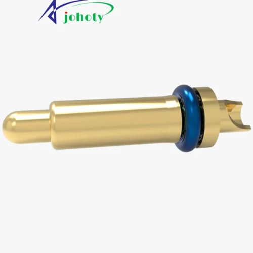
Barrel diameter: Johoty can customize barrels ranging from 3.00mm to 16.00mm, which increases lateral force resistance by three times.
Installation: Johoty large pogo pins eliminate torque offset during vibration through threaded riveting and flange positioning.
Vibration resistance: When subjected to 20G RMS random vibration, Johoty large pogo pins have high contact stability and can meet the EIA-364-28 standard.
Coating: We can achieve hard gold and bottom nickel, which can increase the wear resistance and lifespan of large pogo pins by 200%. Johoty can achieve a lifespan of 500,000 cycles, and its functionality is very stable when connected at high frequencies.
Floating Large Pogo Pins Module
Radial floating: ±0.50mm, compensating for the cumulative installation error when large pogo pins are parallel.
High pressure reduction: single pogo pin stroke of 5.00mm, suitable for gap fluctuations during docking of large-sized equipment,
Multi pin coplanarity: ≤0.05mm, ensuring that all large pogo pins conduct simultaneously without any suspension.
Current sharing: The total current of the parallel module is 200A+, and the current deviation of each pin is less than 8%.
High Temperature Large Pogo Pins
Working temperature: -55°C~+350°C, spring material made of high nickel alloy, no stress relaxation.
Hot plugging tolerance: Under 80A conditions, it can be plugged and unplugged continuously for 500 times without melting or oxidation to increase resistance.
Resistance drift: Resistance change ≤1mΩ after 120 hours of salt spray and high temperature/humidity testing.
Applications for large pogo pins
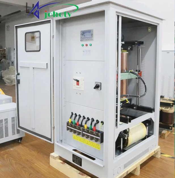
Industrial power connection:
Large pogo pins can continue to conduct, while ordinary terminals are prone to excessive temperature rise.
Working stroke of 2.50-3.50mm, contact resistance is stable at 10mΩ, even 0.5mΩ.
For insufficient rebound caused by spring fatigue, Johoty can design contact force attenuation <3% after 10,000 cycles.
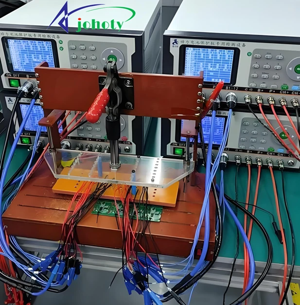
Energy storage & battery testing:
Many customers require a single pin that can withstand transient currents of 50-200A.
Contact area and coating thickness are crucial design factors. Generally speaking, hard gold ≥1.27μm can prevent micro motion wear under high current.
The maximum risk is the possibility of local overheating caused by oxidation. Johoty adopts a 4-wire Kelvin structure to monitor contact resistance drift in real-time.
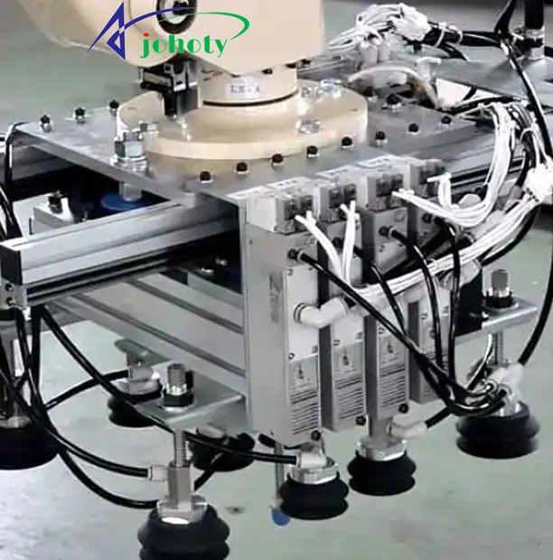
Automated Fixture:
Large pogo pins can ensure alignment tolerance and avoid testing errors. There is a high advantage in reducing NDF.
Radial float ±0.50mm, guide length ≥10.00mm.
When the lateral force causes the barrel to jam, Johoty uses high hardness beryllium copper tubing and precision rolling closure. If necessary, forward sliding can also be used to avoid radial oscillation.
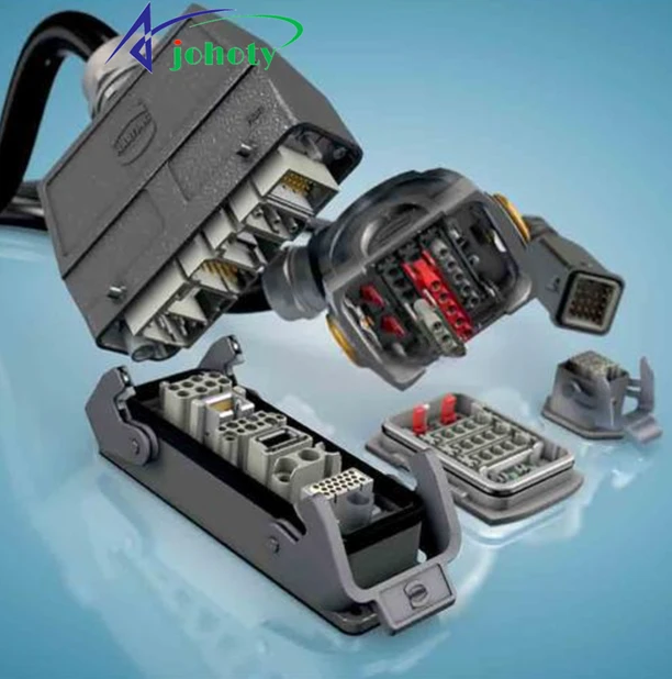
Reloading Docking Module
This type of equipment requires high mechanical strength and electrical conductivity because they have significant impact on docking.
Overloading requires a preload of 30% -40% of the effective travel to prevent sudden disconnection during docking. At the same time, heavy-duty equipment can only be stably connected when the work travel accounts for 60% -70% of the total travel.
Johoty will design a dual spring structure that can maintain conductivity even when a single spring fails. We can avoid the instantaneous open circuit caused by overload settings under high vibration.
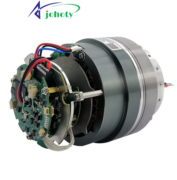
Robot module connection
Robots require high current and long lifespan for robots in repeated docking and limited space.
Their lifespan requires at least 20,000 cycles, with a contact force of 5-8N/pin.
Wear and tear result in exposed gold or nickel coating. Johoty adopts hard-gold and nickel-based plating to enhance wear resistance of our large pogo pins by 3 times.

Vehicle-mounted high-vibration connection
At vibration frequencies of 10-2,000Hz, ordinary elastic connections are prone to micro-motion wear.
Johoty can design a minimum working compression of ≥1.50mm and maintain a static contact pressure of >3N. By combining magnetic attraction structure and hard gold 1.27μm, a magnetic force of 60N can be achieved. Under the combination of 15N force, Johoty large pogo pins can easily meet the requirements of high vibration in vehicles.
This can solve the resistance jump caused by micro corrosion. Johoty conducted 24-hour mixed gas corrosion testing and vibration table online monitoring.
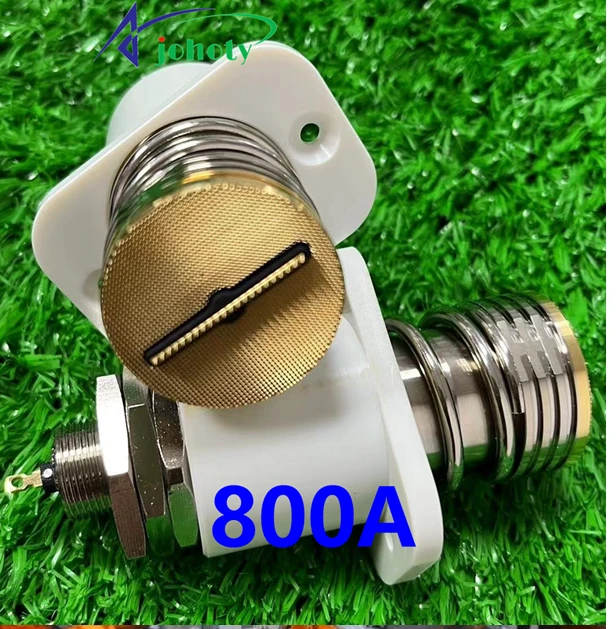
High current charging/discharging module
Single pogo pin continuously flows 30-800A, and the customer needs to control the temperature rise to ≤30°C.
Johoty designs barrel walls with a thickness of ≥0.30mm, using oxygen free copper or beryllium copper, silver plated or hard gold plated.
We specifically address the issue of localized welding caused by current concentration. Johoty adopts a multi-point touch finger structure, also known as a crown plunger tip, and uses 2-level connections to disperse current density.
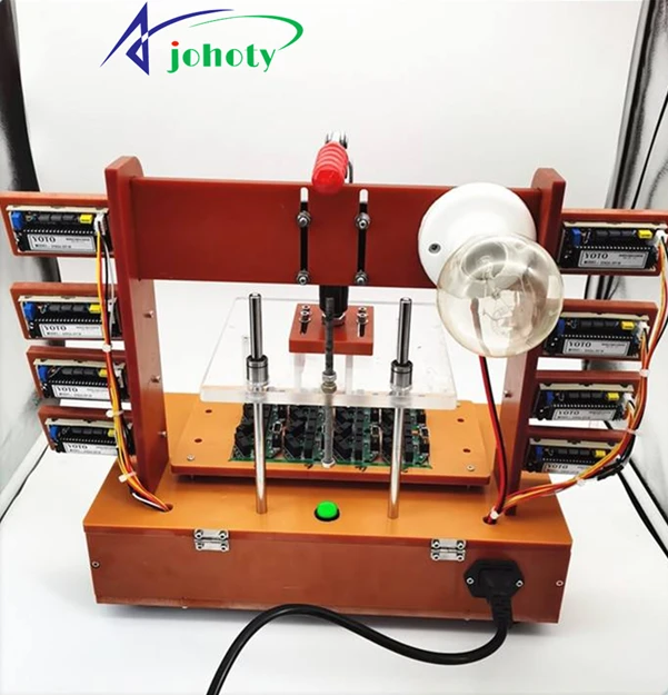
High current testing fixture
The customer requests convenient and fast replacement of DUT, and the high current contact needs to balance convenience and low impedance.
Johoty has designed a spring force of <25N/pin, but the contact resistance remains stable at 15mΩ. If the volume allows, we can easily achieve 0.30mΩ.
The customer does not want excessive insertion and extraction force to damage the PCB pads. Johoty optimizes the spring stiffness curve, with a gentle initial force and sufficient end force.
Installation hole size and tolerance of large pogo pins
The installation holes of large pogo pins determine the holding force, coaxiality, effective compression, contact resistance, temperature stability, and lifespan. They exhibit the best electrical and mechanical performance when operating at rated stroke. Insufficient compression can affect electrical performance, and approaching full voltage can shorten lifespan. Lateral force and misalignment can directly damage the plunger and barrel.
The hole of large pogo pins is locked with near zero clearance:
Aperture: The aperture of the large pogo pin is equal to the outer diameter D~D+0.02 mm.
Hole tolerance: The conventional hole tolerance is +0.00/+0.02 mm. For large pogo pins with high vibration, high insertion and extraction force, and high current, Johoty recommends tightening to +0.00/+0.01 mm.
Hole depth: When large pogo pins have shoulder structures, the PCB hole depth should cover at least the complete locking section. The bottom of the blind hole needs to reserve assembly allowance to avoid eating up the effective compression capacity after the bottom is dead.
When PCB copper plated holes are pressed in, large pogo pins need to follow the retention geometry:
PCB copper plated holes: Johoty will prioritize defining large pogo pins according to the compliant and multi faced press fit rules.
Plastic, insulated seat, non plated holes: define Johoty large pogo pins according to the barb/knurl rule.
Do not mix logic: stuffing the bite shaped shape into an inappropriate plated hole will make it very difficult to control production fluctuations.
Key points of hole design for large pogo pins
Press in type:
Johoty DOE found that excessive holes can cause large pogo pins to loosen, sway, and experience slight displacement wear. The task of the hole is to provide holding force and initial coaxiality. You need to confirm the outer diameter, embossing, and barb height, not just the barrel or large pogo pins themselves.
Welding type:
It is best to increase shoulder position, step or additional support for large pogo pins. Because the holes are mainly designed based on the tail pins of large pogo pins, and the solder joints are responsible for conductivity and reinforcement. Johoty does not recommend letting the solder joints bear the long-term lateral load of large pogo pins alone.
Threaded fixed type:
Johoty designs the retention force of large pogo pins through threads and shoulder surfaces, without relying primarily on the hole wall. Threads can effectively design positioning holes, seat surface perpendicularity, and resistance to loosening, without being too tight when pressed in. Therefore, choosing Johoty large pogo pins is very suitable for large travel, high thrust, maintainability, and frequent replacement.
Customized seating style:
Based on numerous designs, Johoty believes that this is the most stable and effective solution for large pogo pins. We often design step holes, shoulder positioning, anti-rotation, dual guidance, and reference holes. In this way, it can effectively lock the aperture, install height, be coaxial, and prevent tilting. Johoty emphasizes the use of guide pins, alignment tools, and reference holes to stabilize the position and projection height of the receptor.
Design different holes for different substrates:
PCB copper plated holes: Johoty doesn‘t recommend hard fitting the barb inside as it is more suitable for compliant/polygon press fit or soldering tails.
Plastic/insulated module/non plated hole: This is more suitable for barb/knurl as they are interlocked against the hole wall.
Metal seat body: If there is a large lateral load on the large pogo pins, Johoty suggests using stepped holes or threaded seats instead of relying solely on single-stage friction to maintain them.
Insulation module: Johoty will prioritize adding reference holes, guide pins, and anti-rotation structures to cut assembly errors from the source.
Compression and working stroke of large pogo pins
Free Height: The reference length in an uncompressed state, serving as the starting point for all tolerance calculations.
Full Stroke: The theoretical maximum stroke from free altitude to complete crushing, and work is prohibited within this range.
Recommended Working Stroke: The 50%~70% range of the total stroke is the golden balance point between contact force and lifespan. How much pressure is considered true contact stability? 50%~70% of the total itinerary. At this point, the contact force reaches the rated value and can effectively resist oxide film and micro vibration.
Minimum Compression for Stable Contact:
≥15% of the total stroke, ensuring that the positive contact pressure is sufficient to penetrate the surface oxide film. Why does too little pressure cause sudden breakage? When the total travel is >15%, insufficient contact force, micro movement or impact can cause contact surface to instantly separate. Formation of ns level transient interruption, which the system cannot detect but the fault has occurred.
Maximum Continuous Working Compression:
≤80% of the total stroke, leaving a safety margin for mechanical stress and current temperature rise. Why does the lifespan drop quickly when there is too much pressure? At 80% of the total travel, the spring stress exceeds the limit and the material accelerates fatigue. At the same time, the lateral force of both barrel and plunger increases dramatically, causing wear on the coating and shortening its lifespan to <20%.
Over Compression Risk:
After exceeding 80% of the total stroke, the spring enters the plastic zone, the contact force drops sharply, and the lifespan drops sharply. Contact force and compression is linear within their rated range. For every 10% compression of the total stroke, the contact force increases by 12%~15% of the rated value. Within the range of 50%~70%, the lifespan can reach over 100,000 cycles. For every 5% increase in compression of the total stroke, the lifespan decreases by approximately 30%.
Dynamic Compression vs Static Compression:
Under dynamic working conditions, there is slight displacement at the contact point, and the working compression amount needs to be increased by an additional 10%~15% of the total stroke to maintain normal force. Is the static compression sufficient when there is vibration? Not enough. Static design compression requires an additional 10%~15% of the total stroke. Used to compensate for contact point displacement under dynamic conditions, otherwise transient breaks will inevitably occur during vibration.
Compression Tolerance Stack Up:
Johoty provides compression chain analysis based on mechanism tolerances. Ensure that the actual compression still falls within the safe zone under the worst tolerance of the parts. Johoty suggests placing the work compression point at 60% of the total stroke, leaving a tolerance absorption capacity of ±10% of the total stroke for both upward and downward directions. In this way, large pogo pins work in the optimal range during mass production.
Spring force of large pogo pins
Single pogo pin mechanics:
Initial Force: When the Lunar tip is first touched, the force value is extremely small, and it will not push the shell or tilt the fixture.
Working Force: Accurate compression force value and controllable insertion and removal feel. How much will the power drop after long-term use? Controllable range, force attenuation does not trigger failure threshold within the lifespan.
Peak Force: Full spring force controllable, no sudden changes, no cracking of plastic shells, and no tilting of equipment.
Force displacement curve: Johoty can achieve linear, predictable, and batch consistent performance for our large pogo pins.
Total force of pogo pin connector
- Force per pin x number of pins=total applied force. If it is too large, will it cause the structural components to deform? Johoty designs large pogo pins based on customer shell stiffness and synchronously verifies their total force and structural strength.
- 20, 50, and 100 large pogo pins can be compressed simultaneously to accurately calculate the total force. What is the relationship between this and assembly efficiency, fixture lifespan, and after-sales failure rate?
- Large pogo pins with stable force values can ensure that the fixture does not tilt or get stuck during assembly. Customers’ after-sales service will not be repaired due to poor contact or structural damage.
- Johoty can provide you with force analysis of installation direction to avoid structural deformation or positioning failure caused by asymmetric layout.
Mechanical stability:
- Under bias and oblique pressure, Johoty large pogo pins can maintain contact stability without instantaneous breakage.
- The force attenuation curve of Johoty large pogo pins after repeated compression is controllable, and effective contact force can be maintained after fatigue.
- Johoty large pogo pins do not experience increased contact resistance, signal or current abnormalities due to spring aging.
Current carrying and temperature rise of large pogo pins
Large pogo pins (5A~1,200A) have continuous current carrying and controllable temperature rise. Multi parallel pogo pins have uniform diversion and clear derating in the entire temperature range. They have also non-destructive contact under high vibration of 10G or higher. Johoty can ensure that high current and large size are no longer your engineering risks.
Rated current: Johoty can design continuous 50A high current pogo pins with a temperature rise of ≤30°C at 25°C .
Instantaneous capability: Peak value of 80A, pulse width ≤1s, our large pogo pins have no plastic deformation.
High temperature derating: Johoty can design large pogo pins with continuous 25A at 60°C and 20A at 85°C. If you need Johoty to customize high temperature pogo pins, we can achieve 10A at continuous 350°C. We can provide a complete derating curve to ensure system thermal safety.
Temperature rise: Johoty customized 50A large pogo pins are continuously powered on to achieve thermal stability with ΔT<30℃. The design can concentrate the head in pogo pins, isolated it from the housing. And the measured temperature rise of the PCB pads is less than 8°C.
Compression amount:
Johoty recommends a common compression of 2.00mm with a contact resistance of ≤30mΩ. Of course, we can also achieve a minimum compression of 0.10mm. Compression increased from 1.50mm to 2.50mm, with resistance change of <0.1mΩ and temperature rise fluctuation of <3°C. Johoty can provide compression amount, resistance value, and temperature rise curve graphs. You can see the contact stability of our large pogo pins.
Multi pin parallel connection: 4-pin parallel connection, total current 200A, maximum current deviation of single pin<8%. Johoty can provide parallel temperature rise comparison, so you can find that there will be no local hotspots.
Materials and Coatings: A common solution is to deposit hard gold and bottom nickel, with a contact interface hardness of ≥150HV. We can achieve lifespan >10,000 times for large logo pins with resistance value of ≤50mΩ. There is no risk of coating migration or adhesion under high temperature and high current conditions.
Thermal stability: It is rare that Johoty can achieve continuous 2-hour large pogo pins with ΔT≤2°C. Under vibration at 10-2000Hz and 5G, the instantaneous fluctuation of contact resistance is <0.2mΩ without instantaneous interruption.
Contact Resistance for large pogo pins
Johoty designed the contact resistance of large pogo pins, which not only provides the initial milliohm value. We will simultaneously define the initial value, stable value, drift value, vibration value, and the change value after environmental stress. Enable engineers to truly determine whether it can be installed, whether it can carry current, and whether it can be stable for a long time.
Initial Contact Resistance
Refers to the initial resistance value of large pogo pins during initial assembly, specified compression, fixture, and mating material. This is not contact resistance during long-term work.
Stable Resistance After Cycling: After a specified number of compression cycles, the resistance value enters a stable state. This is closer to the actual contact resistance during mass production than the initial value.
Resistance Drift Over Time
Large pogo pins Johoty suggests looking at the drift amplitude, only the initial measurement value, which is not very meaningful. It is the change of resistance value after long-term on-off, current carrying, stress relaxation and change of surface facial mask layer.
Resistance Under Vibration
This is a very important issue for many customers in drone and motor projects. It is the transient contact fluctuation of large pogo pins under vibration and impact. Johoty will focus on the average milliohm value and avoid the risks of instantaneous breaks, peak fluctuations, and micro arcs.
Low level Signal vs High current
The same resistance value has completely different meanings in different applications. For low-level signals, Johoty will avoid transients, noise, and unstable film layers. When applying high current, Johoty will focus on heating, voltage drop, and local erosion.
Resistance Under Different Compression
Lightly press the plunger tip, it is obvious that the compression stroke is insufficient. At this point, contact area of plunger tip is small, contact resistance is high, and the fluctuation is large. When press plunger tip to working height, contact impedance of large pogo pins is the lowest and most stable. Once the pressure reaches full stroke or even more, the results won’t be better. It will accelerate the wear and impedance drift of the plunger tip.
Resistance After Environmental Stress
This refers to the change in resistance of large pogo pins after high temperature/humidity, thermal shock, and salt spray. It is often caused by oxidation, corrosion, and coating degradation of the plunger tip. This determines whether large pogo pins can work in industrial environments.
Vibration and reliability of large pogo pins
Johoty’s large pogo pins are not just about enlarging the size. We conduct verifiable mechanical reliability design for vibration, impact, bias load, instantaneous breakage, pin jamming, and fatigue failure.
Mechanical Shock:
The basic requirement for Johoty’s design of large pogo pins is that they will not bounce at the moment of impact. We can avoid instantaneous breakage, structural deformation, coating damage, and spring instability. Therefore, you will not see direct breakage and instantaneous disconnection of our large pogo pins.
Random Vibration:
Large pogo pins should not experience transient breakage, eccentric wear, pin jamming, or contact resistance drift under wide frequency. Johoty large pogo pins have no intermittent discontinuity under vibration.
Sinusoidal Vibration:
Within the resonance zone, large pogo pins are not allowed to experience abnormal displacement, biased swinging, or contact force attenuation. Because Johoty designed stable contact force and low resistance at the resonance point.
Intermittent Discontinuity Monitoring: Johoty has full process transient monitoring and continuous electrical connection under dynamic loads.
Contact retention force and bias load:
Large structures are more susceptible to inertia, eccentric compression, and lateral disturbances. During the compression process, Johoty large pogo pins have sufficient contact force. Controllable plunger motion under partial load, therefore, there will be no inclined wear, scratches, or local jamming.
Anti-jamming and anti-skew wear design:
This is the mechanical reliability core of large pogo pins. Johoty focuses on designing guiding structures, tolerance control, fit clearances, head force forms, and spring axial stability. Optimized large pogo pins, Johoty ensures that they are not easily stuck.
Analysis of Spring Fatigue and Structural Wear:
Under long-term vibration, failure is due to spring fatigue. And contact surface wear, coating damage, increasing resistance, and unsmooth movement. This directly reflects the lifespan of large pogo pins, determining the number of cycles.
Resistance changes before and after vibration:
- What Johoty’s customers often ask for is not the initial resistance value. More customers are asking whether the contact resistance is stable and whether the drift is controllable before and after vibration or impact?
- With stable resistance, large pogo pins can enter the fields of automotive, industrial equipment, energy storage, and robotics.
Appearance wear and coating damage after vibration:
Visual inspection is the basis for failure tracking. Johoty is very concerned about the wear marks and uneven wear direction of pogo pins. And the damaged area of the coating, impact marks on the head, and wear on the mouth of the cylinder. Many customers directly told us that Johoty is conducting failure engineering verification.
Life Cycles for large pogo pins
Mechanical lifespan:
Mechanical Lifespan: Johoty defines the number of cycles under no load and only compression rebound. Simply understood as the pure mechanical lifespan without electricity.
Electrical Lifespan: Johoty defines the number of cycles with rated current and actual contact heating. After being powered on, it may generate heat, temperature rise, arc, and other actual service life.
For large pogo pins, what Johoty offers you is how many times it can work stably. The conditions for stable operation are specified compression, current, temperature rise, and vibration.
Attenuation curve:
Force attenuation: The decrease in spring force with the number of cycles. Medical equipment, precision instruments, or aviation equipment often require SUS631 and Inconel springs with low force attenuation. Johoty can achieve a 1% attenuation after 10,000 cycles.
Resistance drift: The upward trend of contact resistance with the number of cycles. This impedance stability is very strict, and Johoty can achieve from 30mΩ to 50mΩ after 50,000 life cycles.
Coating wear: Changes in coating thickness/wear morphology in the contact area. A needle plated with hard gold, HV150, Easily achieve a lifespan of 500,000 cycles.
Instant interruption risk: The probability of intermittent contact under vibration or slight displacement is extremely low. Easily cope with 10G acceleration under high elasticity.
Generally speaking, large pogo pins or standard spring loaded pins will not completely break down at once. Johoty’s expertise is to prevent poor resistance, insufficient force, and occasional momentary breaks in pogo pins.
Lifespan classification:
Large pogo pins, at 60% and 90% travel, the lifespan is not of the same level. Johoty suggests that the lifespan of large pogo pins must be divided into at least 5 categories:
Working Stroke Life Cycles, life at recommended compression.
Max Compression Life Cycles: Life at high compression/near full stroke.
Life under Side Load: Life under lateral load/lateral force.
Life under Current Load: Life with current carrying.
Combined Life: Life cycles under compression + current + temperature rise + vibration.
FAQ
Many customers of Johoty have found that the true determinant of assembly stability is not a single outer diameter. But rather the overall matching between the barrel OD, hole tolerance, working stroke, and preload of large pogo pins.
If the aperture is too tight, it can easily lead to excessive compression stress, barrel deformation, and unstable spring movement. If the aperture is too loose, micro displacement may occur under vibration or impact. This leads to fluctuations in contact resistance and a decrease in lifespan.
Johoty needs to know the installation method, working stroke, and long-term tolerance stacking risks when designing large pogo pins. We know that the key is not whether we can fit the large pogo pins in. But rather whether large pogo pins can maintain stable contact force and consistent resistance after batch assembly, tolerance fluctuations, and long-term cycling.
What Johoty can tell you is whether large pogo pins can really carry high current, it’s not just about the rated current. You need to confirm the initial contact resistance, contact stability after full voltage. And continuous temperature rise during power on, and transient peak current.
Because the large pogo pins can be powered on during the sample stage, it does not mean that they will be stable after mass production. Especially under high duty cycle, continuous load, accumulated temperature rise, and contact surface wear conditions. Once the contact resistance is high, large pogo pins will experience local heating, coating degradation, spring degradation, and long-term failure.
Johoty will measure resistance under working stroke and temperature rise under target current. We will also retest the change in contact resistance after 10,000 and 50,000 cycles.
This helps you quickly determine whether large pogo pins are suitable for your power supply, energy storage, industrial equipment, or high-power connections.
This is the key factor for many customers of Johoty to ultimately decide to purchase our large pogo pins. Because once a large connection enters an actual device, it not only has to withstand compression, but also vibration, bias load, lateral force, instantaneous impact, repeated plugging and unplugging, and long-term fatigue.
A truly professional assessment of large pogo pins, Johoty suggests that you:
- How much compression is required for cycling, how much contact resistance drifts, and how much spring force decays. And whether there is instantaneous breakage after vibration, whether the needle gets stuck or breaks after eccentric force.
Johoty focuses on helping clients identify these risks in advance in the large pogo pins project:
- Is the structure of large pogo pins resistant to eccentric loads and can the spring withstand high cycle fatigue? Does the contact interface maintain continuous conductivity under vibration? Can large pogo pins maintain stable lifespan under the combination of high current and mechanical cycling?
For customers who truly value reliability, it’s not just a supplier who can solve these problems. This is definitely a partner who truly understands the failure mechanism of large pogo pins engineering.