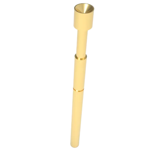
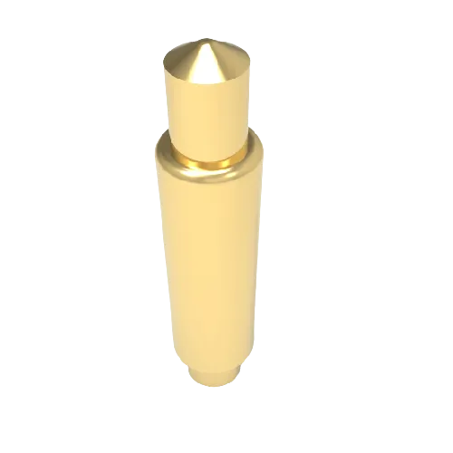
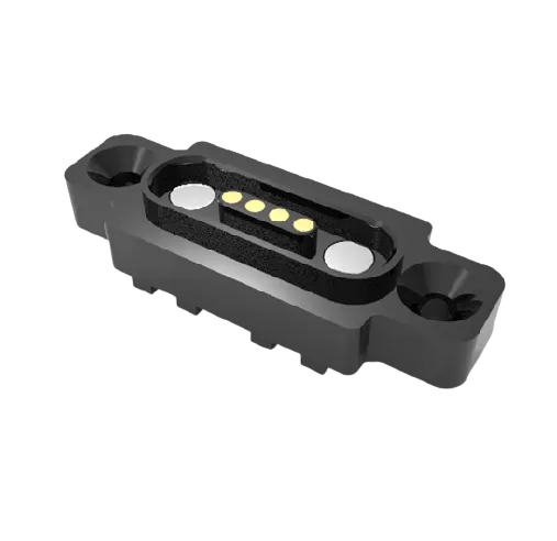
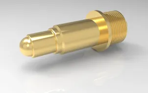
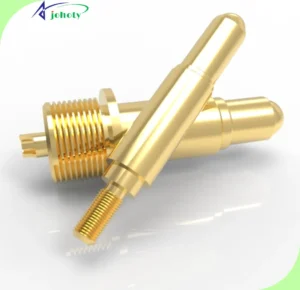
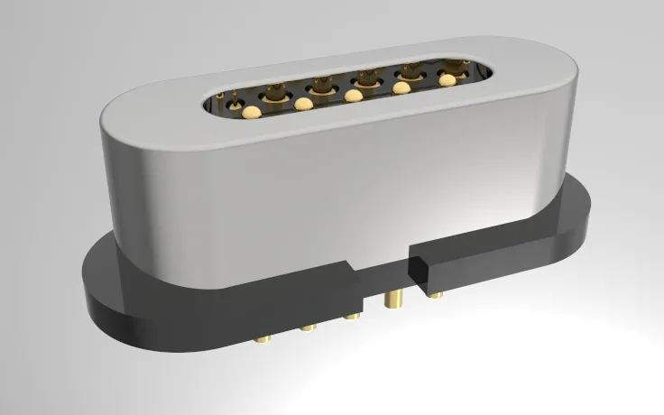
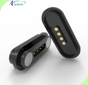
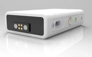
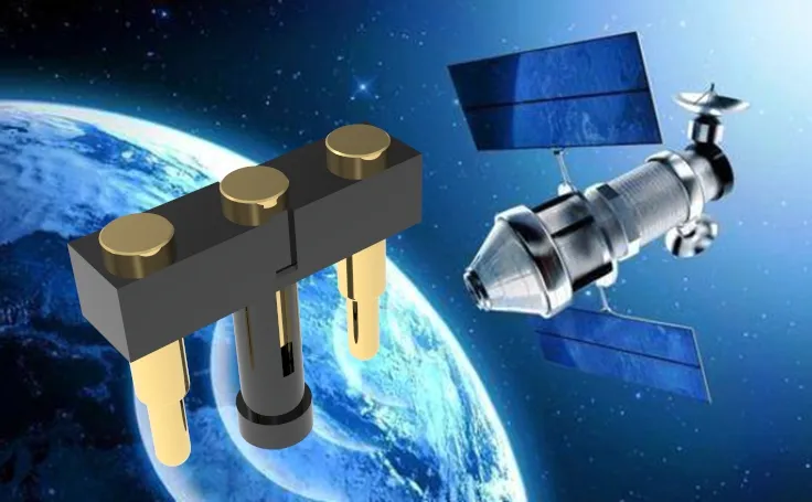
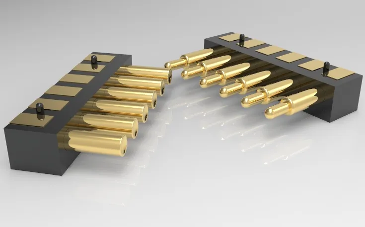
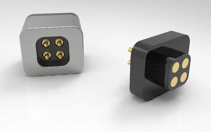
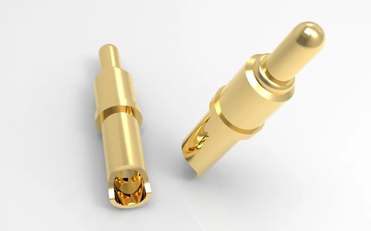
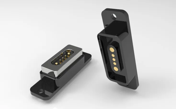
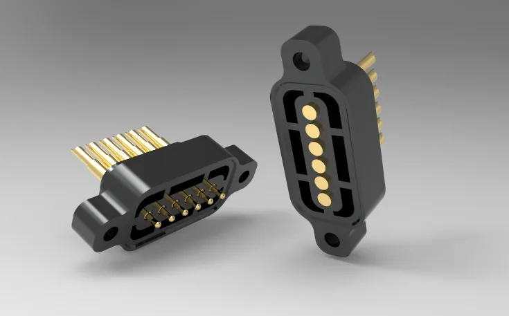
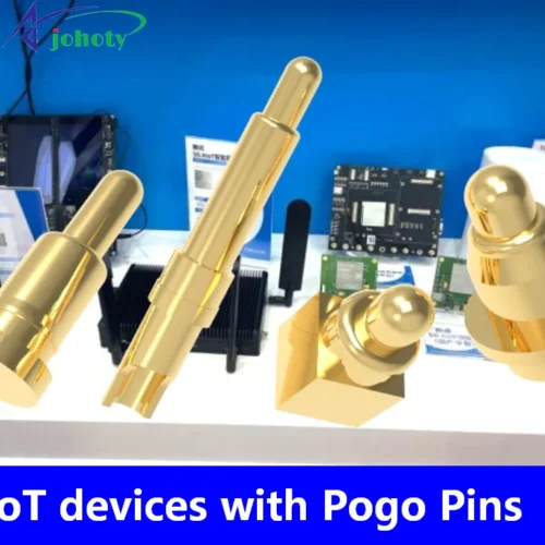
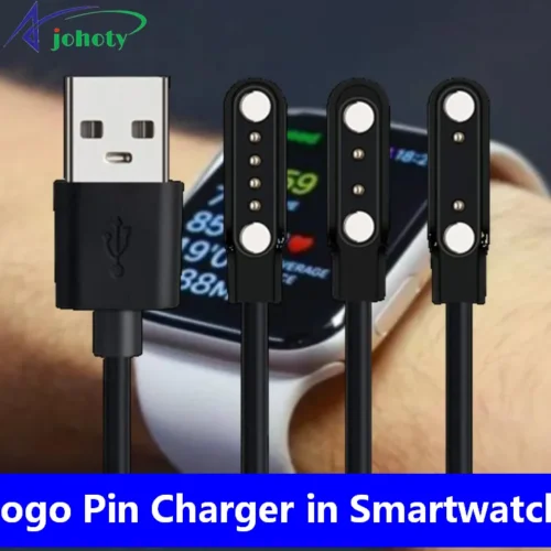
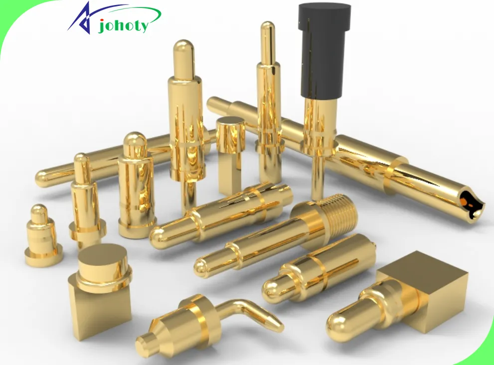
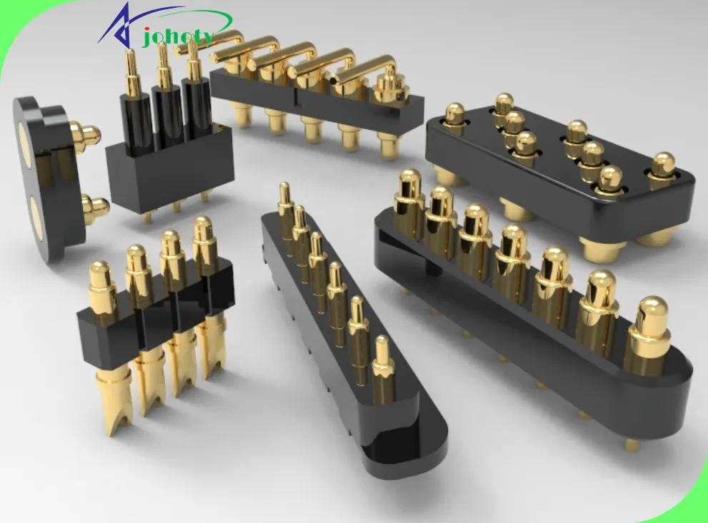
Pogo Pin, Our Tailored Connectivity Technology, Designed Specifically for Your Business Needs. Unveiling Our High-Performance Pogo Pin Solutions, Boosting Connectivity Reliability, Driving Business Growth!
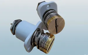
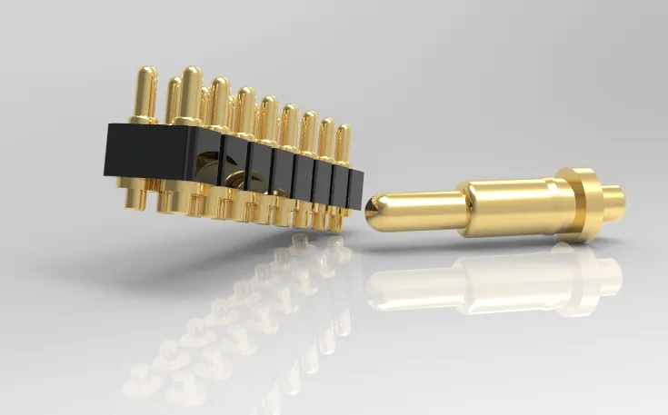
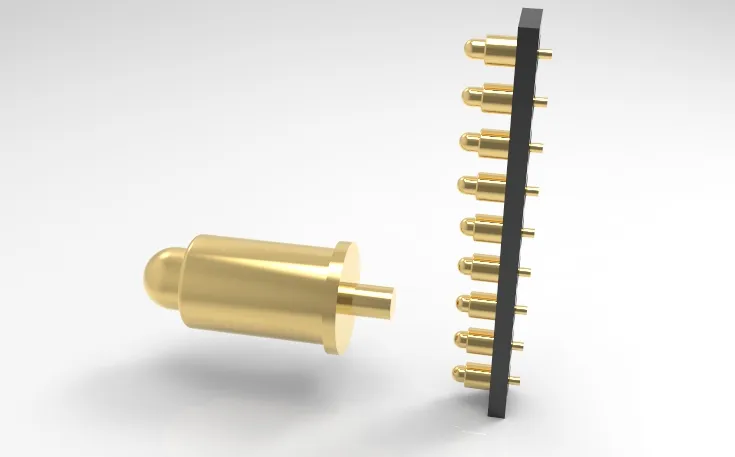
Pogo Pin technology stands as a testament to our robust R&D capabilities and streamlined production methods. Delivers revolutionary connectivity solutions for various industries. With over 20 years of industry experience and substantial technical expertise. Our R&D team is dedicated to crafting innovative Pogo Pin designs, continuously pushing the performance boundaries of our products.
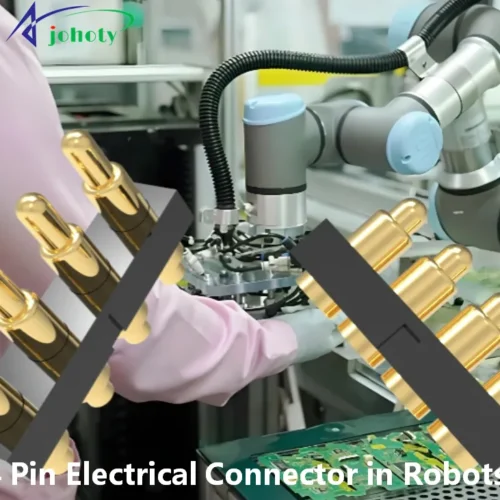
Pogo Pin, our core strengths lie in cutting-edge R&D, efficient production, quality assurance, and customization capabilities. We cordially invite you to collaborate with us and experience high-performance Pogo Pin solutions provided by true industry leaders.
What Solutions Can We Offer?
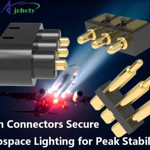
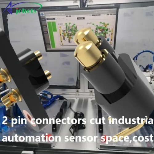
We offer end-to-end bespoke solutions, guiding clients from concept to finished product, aiding in product innovation and market success. Ideal for industries with stringent specifications and high-quality demands, such as the automotive, aerospace, medical, electronics, etc.
Ⅰ. Design and Development:
Engineering Design Support: Provision of engineering drawings and formulation
Read More
show less
Ⅱ. Mold Manufacturing:
Custom Mold Design: Tailoring specialized molds according to client
Read More
show less
Ⅲ. Material Selection:
Material Consultation: Offering professional advice to aid clients
Read More
show less
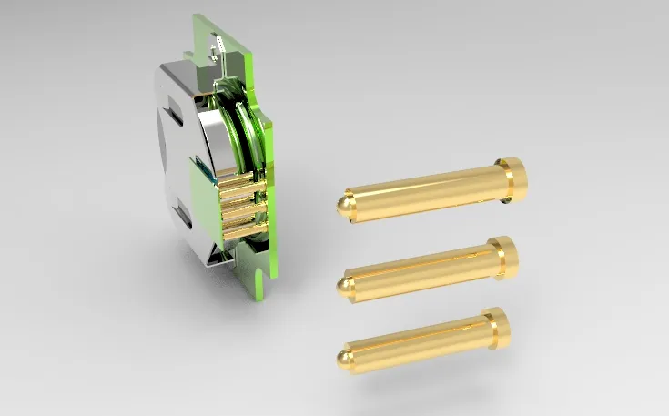
Ⅳ. Precision Machining:
CNC Machining: Achieving high-precision machining through
Read More
show less
Ⅴ. Quality Control Testing:
Dimensional Measurement: Using precision measuring tools to ensure
Read More
show less
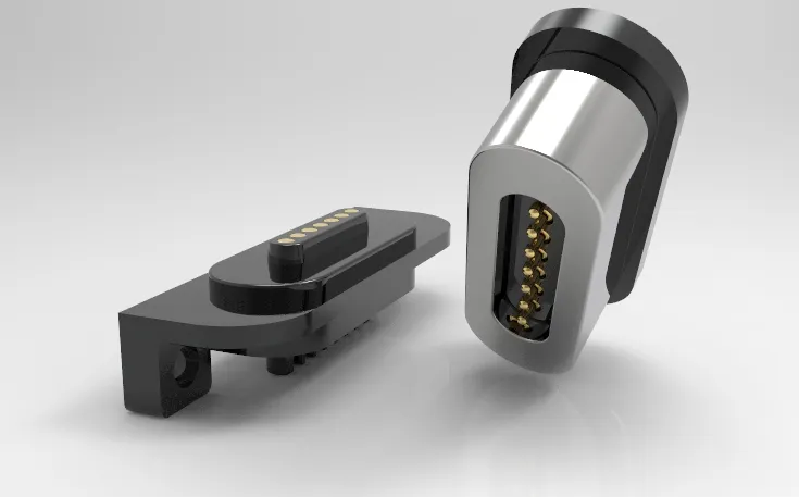
Ⅵ. Assembly and Functional Integration:
Component Assembly: Providing assembly services ranging from simple
Read More
show less
Ⅶ. Logistics and ASS:
Customized Packaging: Providing professional packaging according to product
Read More
show less
Ⅷ. Small Batch and Large-Scale Production:
Flexible Production Capacity: Offering the flexibility to switch from
Read More
show less