Micro Pogo Pins Enable Ultra-Compact, High-Reliability Contact for Medical, 5G, Aerospace. Validate Specs. Download Datasheet. Request Samples!
Introduction:
Micro pogo pins, they are driving the evolution of electronic devices towards miniaturization, high speed, and multifunctional integration. High Density Interconnect PCB (HDI PCB) has gradually become the core platform for advanced packaging and system design.
Under this trend, traditional connectors are no longer able to meet multidimensional requirements such as space utilization, electrical performance, and mechanical reliability. Johoty can provide precision micro pogo pins with a height as low as 1.29mm, a spring force of 5gf, and a resistance of 10m Ω. They are becoming a key connectivity solution of concern for high-end electronic system design engineers and integration experts.

Overview of micro pogo pins technology
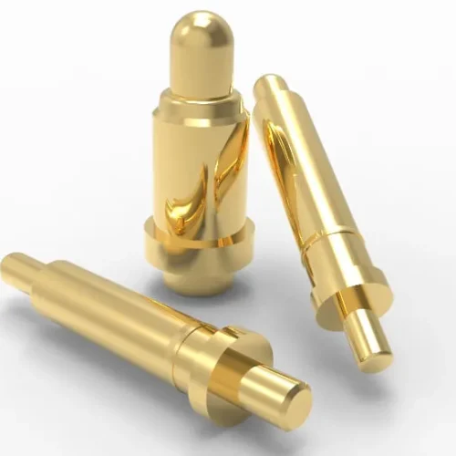
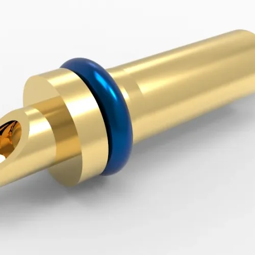
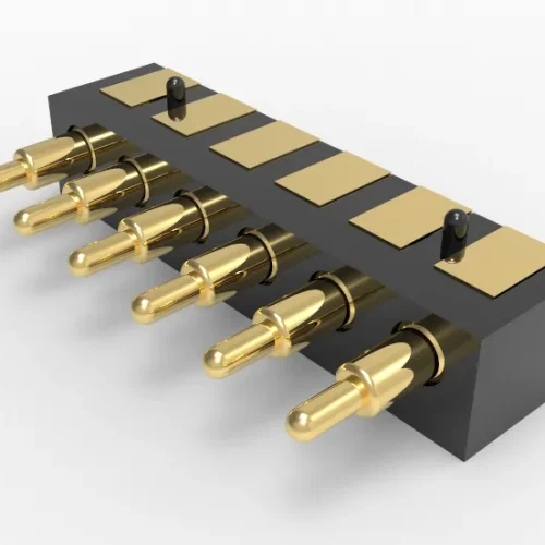
Definition and basic structure: Micro pogo pins are a type of small, repeatable connector based on the principle of spring loading. They are commonly seen in high-frequency testing, board to board connections, module interfaces, and battery connections. Its core consists of three parts: plunger, spring, and barrel, combined with high-precision tolerance control. They have stable contact and long-lasting mechanical action based on a very small volume.
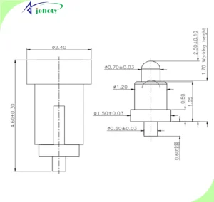
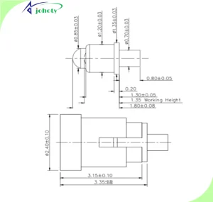
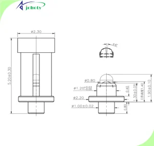
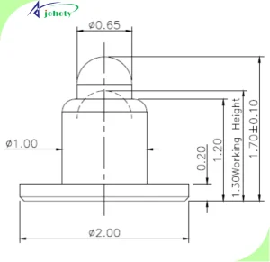
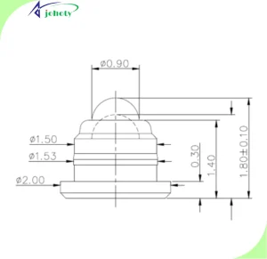
The importance of 1.39mm packaging: In ultra-high density PCB layouts, the area occupied by connectors becomes a bottleneck. The 1.39mm length pogo pin meets basic electrical and mechanical performance requirements, significantly reducing the packaging volume. Suitable for modular products, wearable devices, micro medical instruments, etc.
Design consideration for 5gf working force: 5gf (gram force) represents the minimum elastic force required for the pogo pin to come into contact with the target pad. Too small can lead to poor contact, while too large can easily cause pad wear and displacement. As a minimum elasticity often requested by many customers, 5gf is honestly difficult to achieve. It is an engineering compromise solution supported by ensuring lifespan and reliability data.
Engineering value of 10mΩ contact resistance: In high-speed signal transmission and low-power devices, contact resistance is a key control parameter. The ultra-low impedance of 10mΩ can effectively suppress signal reflection and EMI effects. At the same time, it provides favorable guarantees for power management and grounding design.
Challenges and Countermeasures of Micro Pogo Pins in High-Density PCBs
Space constraints and encapsulation optimization: In high-density design, pogo pins need to be embedded in extremely small mounting holes. At the same time, maintain the manufacturability of welding or plug-in structures. This type of 1.39mm pogo pin often addresses packaging challenges through automated mounting (such as SMT mounting adapter boards), Micro via blind hole optimization layout, and other methods.
Contact reliability and fatigue life: Probe testing for high-frequency plugging and micro displacement contact, module hot plugging require pogo pins to have a mechanical life of over 10,0000 cycles. Johoty often uses precision CNC cutting, high-performance cobalt based or copper beryllium alloy springs, and gold/rhodium plated surface treatments. Ensure high electrical stability and mechanical toughness.
Electromagnetic compatibility (EMC) design: In GHz level high-speed transmission design, pogo pin layout can affect signal integrity and system EMC performance. The high-end applications of customers are usually designed through common ground, signal/power separation wiring, and impedance matching at the end. Optimize the connection system using various simulation tools.
Thermal management and material matching: Under long-term operation, the temperature rise at the connection point cannot be ignored. The 1.39mm pogo pin is made of low thermal resistance alloy and high thermal conductivity shell material HBi59 nickel plated. Combining PCB local heat dissipation slots or copper pillars to assist in cooling is a key step in achieving system thermal stability.
Materials and Manufacturing Processes in the Design of Micro Pogo Pins
Spring and plunger materials: Common spring materials include SWB-P, SUS304, copper beryllium alloy, cobalt nickel based alloy, etc., which have high elastic modulus and fatigue strength. Plunger commonly uses hard brass or titanium copper materials, electrolytic polishing and gold/rhodium plating to enhance conductivity and corrosion resistance.
Barrel structure: The barrel needs to bear all mechanical stresses and is typically made of stainless steel or copper alloy. Surface treatment includes gold plating, nickel/palladium/platinum/rhodium/ruthenium, PTFE coating, etc., to ensure smooth sliding and corrosion resistance.
Microfabrication technology: The production of 1.39mm pogo pins imposes strict requirements on microfabrication processes. The core process system consists of precision automatic lathe, nanometer-level concentricity control, electrical discharge micro hole machining, ultrasonic cleaning, and automatic assembly system.
Electrical performance verification and reliability testing of Johoty’s micro pogo pins
Electrical performance testing:
Initial contact resistance: Typically 10mΩ, often required by engineers.
Current carrying capacity: up to 1-3A, depending on pogo pin length and material.
Signal integrity analysis: TDR test reflection coefficient, in compliance with interface standards such as LVDS/USB/HDMI.
Mechanical life test:
Plug and unplug lifespan: 10,000~100,000 times (depending on load conditions).
Insertion/extraction force: Within 15gf±5gf, Johoty can design a minimum of 5gf, but it may be limited by current and size.
Vertical load/lateral tolerance: Maintain electrical connection under displacement deviation not exceeding 0.2mm.
Environmental reliability testing:
High and low temperature impact: -40 ℃~+125 ℃.
Salt spray test: ≥48h.
Vibration test: 10~500Hz, 3-axis 10 minute/cycle.
Damp heat test: 40℃, 90% RH, continuous contact impedance <20m Ω for 168 hours.
Micro pogo pins engineering applications
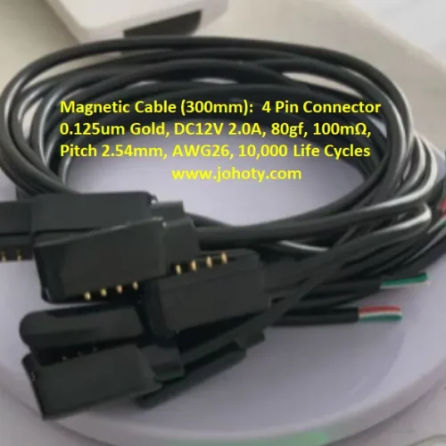
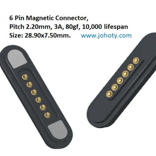
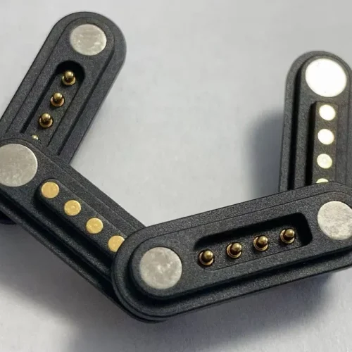
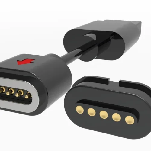
Wearable device module interface: Smart bracelets, health monitors, and other devices require small, stable charging or signal interfaces. Using a 1.39mm pogo pin can improve space utilization and achieve flexible connection with the charging dock or motherboard. It is convenient to replace or upgrade modules.
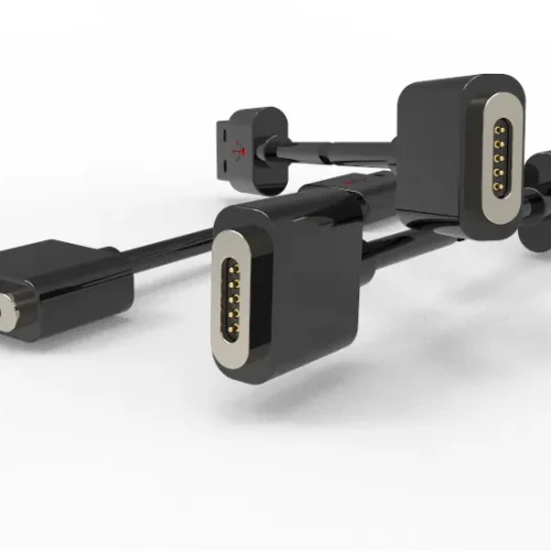
Communication module testing probe: High density communication modules (5G NR sub-6GHz modules) require online automatic testing. A high-precision pogo pin array (matrix layout) can use in an ATE platform interface. Realize high-speed testing with micro spacing to improve production efficiency.
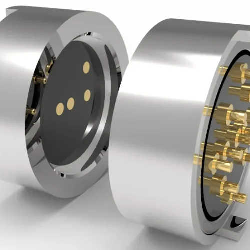
Medical electronic probe interface: Ultrasonic diagnosis, EEG monitoring, and micro endoscopic modules require frequent connection to high-sensitivity signal channels. Pogo pins provide a secure connection that is solder free, replaceable, and has good EMI control.
Internal connections of aviation/automotive control units: In high-vibration and wide temperature working environments, traditional FPC connections are prone to poor contact. Pogo pin connection enables modular assembly. It is beneficial for maintenance, reduces the number of connection solder joints, and improves system maintainability.
Design considerations and simulation analysis
The contact surface size of the plunger: If the contact surface is too small, it will affect the conduction area, and if it is too large, it will cause interference. Johoty will calculate the ratio of the diameter of the plunger tip to the pad area through CAD parameter matching. This can obtain precise and effective needle diameters.
Insertion force on module structure: If not design the insertion force of micro pogo pins properly, it can cause deformation or jamming of the motherboard. In structural CAE, we will incorporate mechanical constraint analysis.
EMI/EMC field simulation: In high-speed signal paths, the pogo pin model simulation will be conducted by Johoty using ANSYS HFSS. In this way, you can identify interference paths and resonance frequencies in advance.
Life prediction and Monte Carlo: Monte Carlo models can use in high-reliability avionics or medical equipment. Simulate the performance changes of pogo pins after 10000 insertions and removals to guide material optimization. For micro pogo pins, high-quality materials always determine their lifespan.

Conclusion:
Micro pogo pins 1.39mm | 5gf | 10m Ω are not just simple micro connectors. But it is a system level component that integrates mechanical miniaturization, high electrical reliability, and engineering optimization of thermal and electromagnetic performance.
The value in high-density PCBs is not only reflected in their small size, but also in the guarantee of overall system performance and long-term reliability. System integrity and design boundaries are often the core concerns of engineers. Micro pogo pins are small components that carry not only connections, but also system level trust.