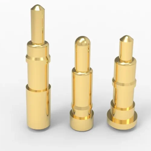
Contact Resistance 10mΩ Pogo Pins Ensure Stable Power Flow Across 100K Cycles In Tight Spaces. Discover Precision You Can Rely On. Get Specs.
Introduction: Why is contact resistance a core variable in compact circuit design?
Contact resistance, in compact connected systems, it is never an overlooked variable. Especially when designing a pogo pin connector with a lifespan of ≥200,000 cycles. It is not a subsidiary item, but a fundamental one.
The contact resistance of pogo pins decreases from 30mΩ to 10mΩ. On the surface, it appears to be a reduction in the number, but in reality, it is a decrease of over 30% in system-level power consumption. Significant optimization that reduces signal drift by over 40% and thermal accumulation by nearly half.
The smaller the space, the greater the thermal pressure, and the denser the current. The mΩ level variation at each touchpoint may become the boundary line between the success and failure of the final product. The 10mΩ pogo pin launched by Johoty was born in this design environment.
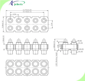
How is contact resistance as low as 10 mΩ achieved while maintaining 100,000 stable cycles?
Increasing mechanical cycles to 100,000 is not a matter of metal strength. It is about the accumulation of fatigue on the contact surface and the stability of micro-displacement.
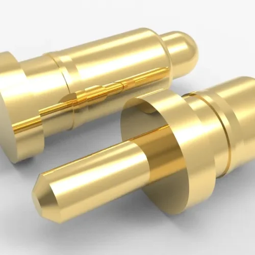
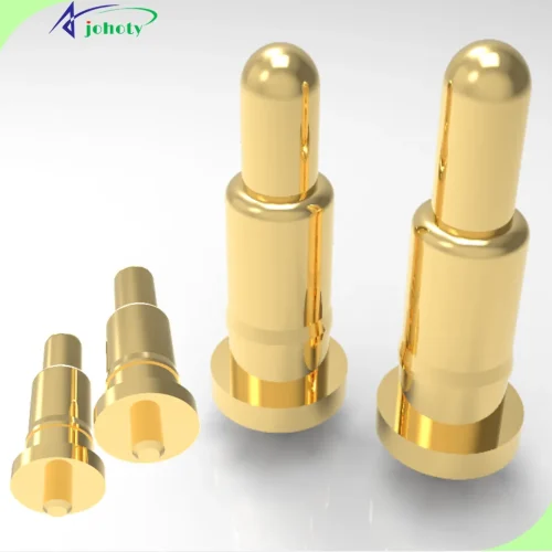
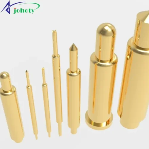
Johoty achieves low contact resistance in pogo pins or pogo pin connectors through a three-layer structure:
- The base uses a deformation-resistant copper alloy to keep the pogo pins secure.
- Middle layer spring is wound from a rare-earth cobalt-molybdenum alloy, with rebound decay <1%.
- Gold plating thickness on the contact points is controlled at ≥30in and validated through testing against the ASTM B689 standard.
After 100,000 cycles under conditions of -40℃ to 125℃, 50g vibration frequency, and low-voltage high-current operation, the contact resistance increase is <1.0mΩ. This average value is based on testing 72 samples across four application categories. After prolonged operation, Johoty’s pogo pins maintain stable contact, low heat generation, and reliable output.
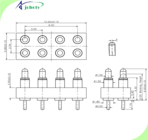
How does precise contact resistance control ensure stable power transmission?
When power is transmitted through pogo pins, high contact resistance will definitely have an impact. Even if it is only a few milliohms, it will form a local hot spot at the connection point.
Take a pogo pin operating at 12V and 3A as an example. Reducing contact resistance from 20mΩ to 10mΩ decreases the thermal power per contact point from 0.18W to 0.09W. If the pogo pins have 100 contact points, the total thermal power consumption drops from 18W to 9W. This represents a 50% reduction in thermal energy, which directly impacts the temperature rise and lifespan of the device housing.
In many cases, customers’ systems require prolonged operation in enclosed structures or low-heat-dissipation housings. This difference becomes a decisive factor in structural design. A structure with low contact resistance allows for thinner heat-dissipation metal layers, reducing overall weight and enabling lightweight circuit modules.
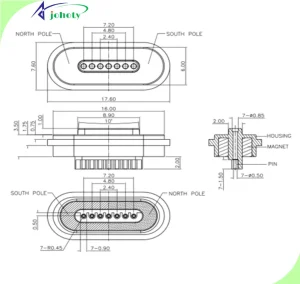
In small spaces, contact resistance is a key factor in reducing structural complexity.
Compact spaces mean:
- Limited pin positions.
- Restricted heat dissipation structures.
- Higher reliability standards.
Johoty’s 10 mΩ pogo pin uses a dual-guide structure. This ensures precise alignment during each compression and rebound, preventing micro-misalignment. Under a microscope, this control manifests as:
- Offset angle <0.5°.
- Vertical deviation <5μm.
- Spring compression and rebound rate error <2%.
As a result, contact resistance fluctuations are maintained within ±0.5mΩ. When used in high-density connection systems, this significantly simplifies module structure design. No additional pressure compensation design or redundant pin array design is required. 10mΩ contact resistance acts as a system-level complexity eliminator.
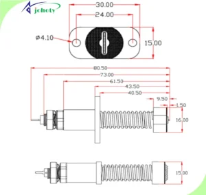
Contact resistance is an implicit variable in electromagnetic compatibility design.
In RF/power systems, people tend to focus on shielding layer thickness, grounding layout, and capacitor filtering. However, it is actually changes in contact resistance that cause fluctuations in signal reference.
In a 5G base station device, Johoty assisted the customer in replacing the original 25 mΩ pin and found that:
- Synchronization clock error was reduced from ±9 ps to ±3 ps.
- Ground voltage fluctuations were reduced from ±0.3V to ±0.05V.
- The average bit error rate of the RF module decreased by nearly 60%.
These figures represent not an improvement but an expansion of the error tolerance margin. This highlights the reality that contact resistance is severely underestimated in the context of electromagnetic compatibility.
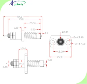
When it comes to lifespan, contact resistance is the technical lever behind cost savings.
Why do many engineers prefer redundant pin arrays? Because they worry that contact aging at a certain point will cause resistance to increase, leading to thermal runaway or signal drift.
However, Johoty’s 10mΩ pogo pin, after 100,000 cycles of lifespan testing:
- The average change in contact resistance is +0.83mΩ.
- Thermal decay growth is controlled within 1.6%.
- The mechanical elasticity decay curve is smooth, with no sudden spikes.
Even without redundancy, a single pogo pin can be used reliably for 3–5 years. By reducing the number of contact points, inspection steps are minimized. The savings come from overall costs of BOM, testing and post-sales, not unit price of single pogo pin.
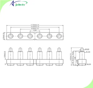
Optimizing contact resistance is a critical system variable in high-precision testing equipment.
Johoty designed a pogo pin connector for a nanometer-level displacement testing platform. The customer’s platform system was extremely sensitive to signal delay and drift. Initially, the testing platform exhibited unstable readings and poor repeatability. After switching to Johoty’s 10mΩ pogo pin:
- Data repeatability improved to 99.96%.
- Signal linear drift values decreased by 84%.
- Voltage response jitter amplitude was reduced by 72%.
Engineers later reported back, stating they had never imagined that the contact resistance of a connector could have such a critical impact on the overall system output. This is precisely the precision philosophy Johoty upholds: not just pursuing low resistance, but pursuing long-term consistency in signal integrity.
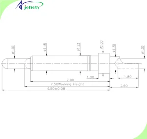
Every milliohm of contact resistance determines the limits of your system.
At Johoty Labs, we treat every pogo pin as a micro-scale bridge. Controlling every milliohm means controlling every energy consumption group. Controlling every transient and the precision of every micro-response.
This is not about sentimentality but a practical necessity as design boundaries are pushed to their limits. Johoty’s 10mΩ pogo pins and pogo pin connectors are not only about low resistance but also about stable resistance. After 100,000 cycles, they remain stable on the same output curve.
Customers often seek long-term system consistency, pure and stable signals, reliable transmission, and thermal control performance. This micro-ohm-level control is the foundational layer that builds customer confidence.
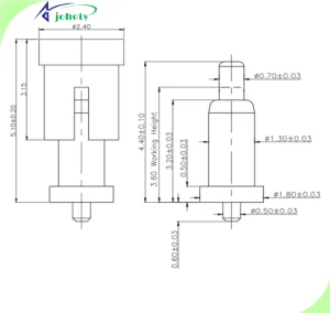
Contact resistance is why you choose Johoty, and it’s the best starting point for a conversation.
Optimizing contact resistance is never the sole responsibility of a single pogo pin; it’s the beginning of an entire system engineering process.
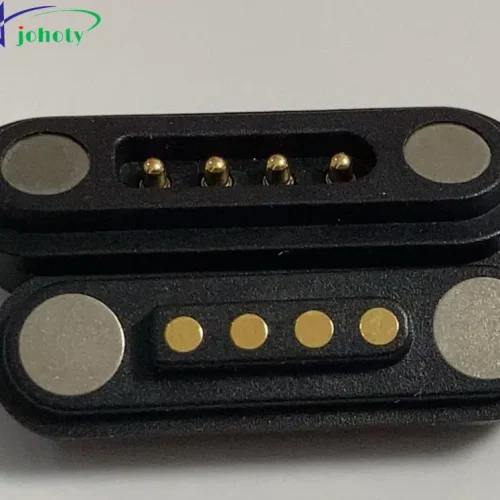
You can continue using older solutions that seem more cost-effective. However, your system will require more thermal management space, redundant connection designs, and excessive tolerance safeguards. When you choose Johoty’s 10mΩ pogo pin, you are selecting a set of pogo pin connectors that have been rigorously tested in real-world environments. You are also choosing an engineering partner that can support the safety margins of your design.
We invite you to test our pogo pins or pogo pin connectors with low contact resistance. We also encourage you to involve our engineering team in design discussions from the early stages of development. The next step begins with a conversation about low contact resistance. Contact Johoty. Start engineering trust.