1. Spring Loaded Pin: Briefs of Function
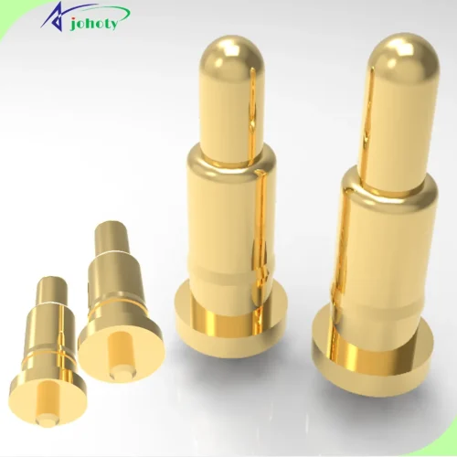
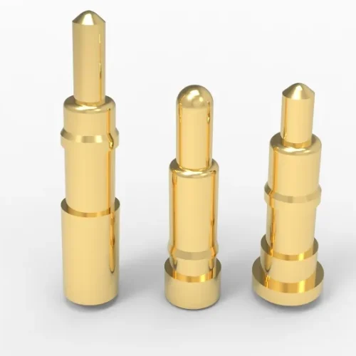
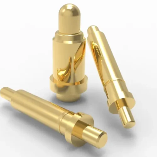
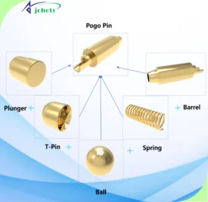
Spring loaded pin, known as pogo pins. It usually contains a plunger, a spring, and a barrel, which are common 3-parts. To realize a special purpose or function, we often design 4-parts or 5-parts by adding a ball or T-pin. The objectives are to generally achieve high current.
Pogo pins have various shapes according to their actual applications. Their surface electroplating is generally gold-plated. Which can better improve their anti-corrosion, mechanical properties, and electrical properties. And adapt themselves to all kinds of working environments.
Spring loaded pins are mainly for current and signal transmission, i.e. charging, conductive pins, switches, and so on. And, they have high durability, stability, and perfect spring force. During they are used in fields of electronics, testing, industries, and so on.
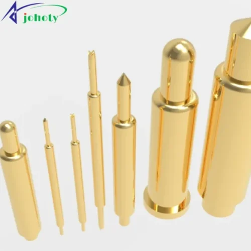
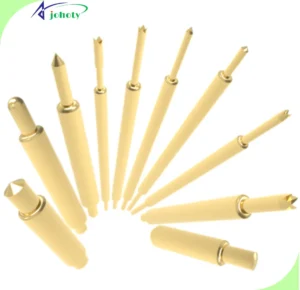
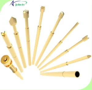
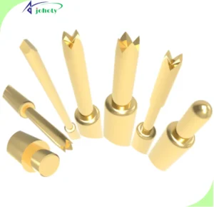
2. What Shapes Has Spring Loaded Pin?
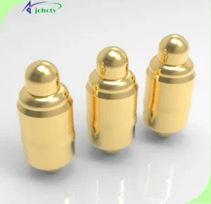
Flat Bottom Type (SMT).
The bottom of the barrel is flat, which has very good stability. And very easy to weld onto the soldering pad of PCB.
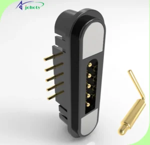
Through Hold Type (DIP).
The end of the barrel is a positioning pin, which is soldered in the through hold of PCBA. So it will not be shifted when soldering with the PCB board. And the positioning effect is very good.
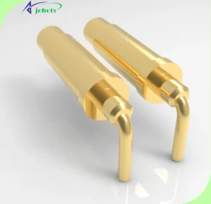
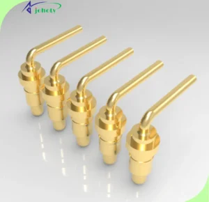
Bending Type.
90° Tail pin bends to provide R&D designers with more options for space utilization.
Solder Cup Type.
The tail comes with a weldable AWG position, that has a mostly notched profile. It is capable of welding AWG 1~46 cable with a current range of 6 mA to 190A.
. 
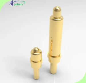
Double Ended Type.
It has the shape of a dual-heads, dual-movement. Allowing R&D engineers more flexibility in board-to-board bi-directional connectivity.
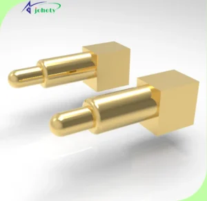
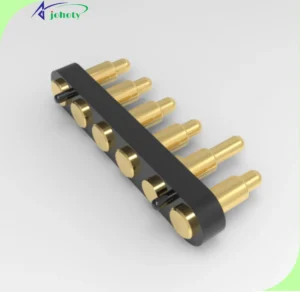
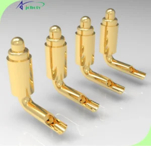
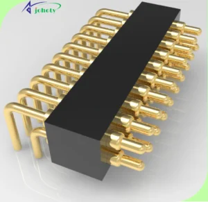
Right Angle Type.
One side of the tail is a functional surface. It is a shape that saves the most height. It gives the electronics R&D engineers maximum freedom in height design.
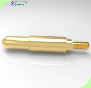
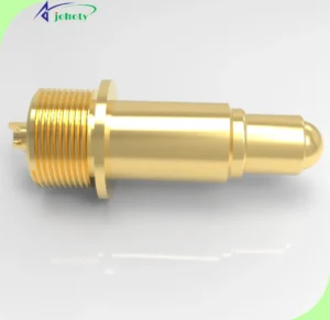
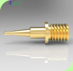
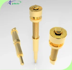
Threaded Screw Type.
A variety of US-gauge or UK-gauge screw threads are designed on the plunger, barrel, or tail pin of pogo pins. They can meet the various needs of customers.
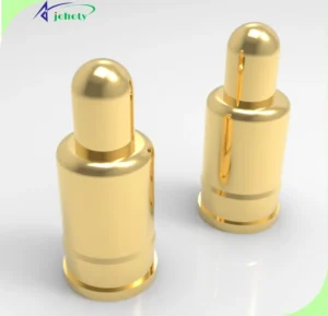
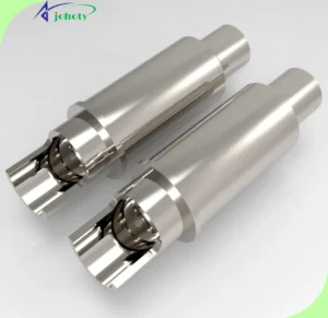
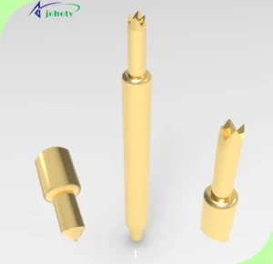
Extending Plunger Type.
Both the plunger and the tail pin are in the same axis center, in and out in the same direction, commonly designed for high currents.

IC Test Probes.
They have also dual-heads, dual-acting. Plunger shapes have balls, cups, crowns, sharp, sharp, domes. And so on. They are for IC tests as test consumptions.
ICT Test Probes.
They are single-head and single-movement. Common plunger tips are sharp, crown, ball, cup, and flat. And so on. They are for the ICT/FCT test as test consumptions.
3. How Does Spring Loaded Pin Solve Lateral Force?
Firstly. Almost all pogo pins else have no effective solutions to solve the lateral force. Except for the construction where the plunger tip is a ball. It can minimize the impact of lateral force within ±55°.
Secondly. Another solution is to increase the stiffness and strength of the pogo pin. It will reduce the impact of small lateral forces.
Thirdly. You have to mount pogo pins in place to minimize the lateral force. If the lateral force is required, the plunger tip with a ball will be perfect.
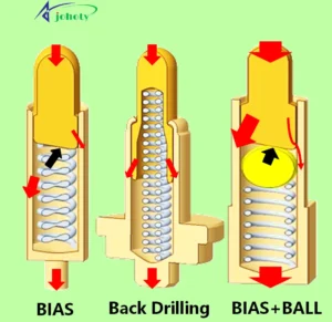
4. About the Inner Structure Of Spring Loaded Pin.
Bias Tail.
The end of the plunger is a beveled edge of 12° or 18°. It will increase the lateral force between the plunger and the inner wall of the barrel. That is, Bias structure can enhance contact stability. Applicable to power supply Pin, for current transmission of <2.0A
Back Drill.
The end of the plunger is a back drill. The spring can be loaded into the plunger back hole to increase the internal spring space. Applicable to the signal pin, for signal transmission.
Bias + Ball or Ball + T-pin.
4 parts or 5 parts design. The plunger is a bias tail, place a ball or T-pin for a high current of 2.0A~10.0A.
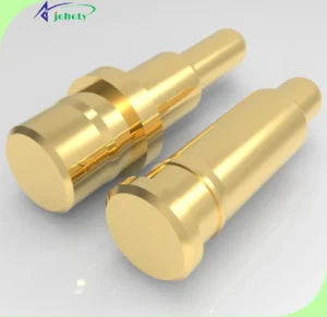
Step or Tail Plug.
It is the structure of extending the plunger. It has very stable and low contact consistency. Greatly drop the risks of instantaneous power failure. It is designed for a high current of 10.0~30.0A.
5. Raw Materials of Spring Loaded Pin.
Plunger and barrel. Brass(HBi59, C3604,C3601;C2680). Tin bronze (C5210; C5191, C5440). Copper beryllium (C17200; C17300). Tellurium copper (C14500), SUS304, SUS316F, SUS316L. We refer to their hardness & cutting machinability. Electrical conductivity, buckling strength. Ductility, cost, corrosion resistance, eco-friendly.
Spring. SUS304 wire, SUS301 wire, SWP wire (gold plated). BeCu wire. FMW1058, Phosphor Bronze. Non-magnetic springs. Insulated springs. We refer to their wire diameter & external dimensions. Elasticity & longevity, kinking condition. Corrosion & temperature resistance, Cost, Environmental performance, etc.
Ball. Stainless steel, brass, zirconium beads, aluminum oxide beads. We refer to their dimensional tolerances, Conductivity, and so on.
Housing. When pogo pins are assembled into multiple pins connectors, the materials include LCP, HTN, PA9T, PA6T, PA46, PBT, PA66, PC+ABS, etc. We often think about their temperature resistance & moisture absorption. Fluidity, molding feasibility, Strength & impact resistance. Insulation & voltage resistance, cost, environmental performance, etc.
6. What is Electroplating of Spring Loaded Pin?
Types. It’s about the electroplating of the sub-part. Including Rack plating or hanging plating. Barrel electroplating. Electroless plating. Evaporation. Continuous plating. Selective plating.
Process.
Step 1. Pre-treatment. It is to remove surface contamination and grease of sub-parts. Its time is about 2 hours.
Step 2.Activation. It is about the removal of the oxidized film. Its time is about 30 minutes.
Step 3. Electroplating. It is about the deposition of metal on the surface of the material. Its time is about 1 hour.
Step 4. Post-treatment, it is to clean up all electroplated parts. Its time is about 30 minutes.
Common electroplating specifications and salt spray testing:
| Sub-part Materials | Coating Thickness | Salt Spray |
| Brass | Au 2u” | 12 hours |
| Au 5u” | 24 hours | |
| Au 10u” | 48 hours | |
| Au 30u” | 96 hours | |
| Au 50u” | >96 hours | |
| CuSnZn:40~80u”, Au:10u”, AH:10u” | 48 hours | |
| CuSnZn:40~80u”, Au:10u”, PdCo:60~80u” | 96 hours | |
| CuSnZn:40~80u”, Au:30u”, PdCo:60~80u” | 96 hours | |
| CuSnZn:40~80u”, Au:50u”, PdCo:60~80u” | 120 hours | |
| CuSnZn:40~80u”, Au:100u”, PdCo:60~80u” | 168 hours | |
| BeCu C17300 | Au 5u” | 24 hours |
| Au 10u” | 48 hours | |
| piano wire | Flash Au | |
| Tin bronze | Au 32u”, 50u” | >96 hours |
| TeBu | Ag 240u” | |
| Brass 3601 | Ni 30~80u”, Pd Ni 6~12u”, Pd 3u” | <48 hours |
| SUS303, 304, 316 | No electroplating | |
| Remarks: 24 hours of salt spray is equivalent to 1 year of exposure to nature. | ||
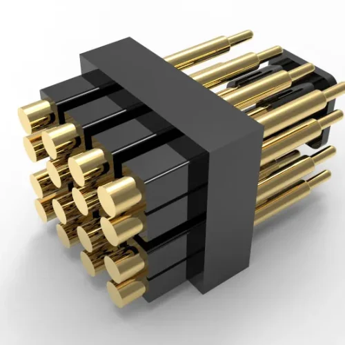
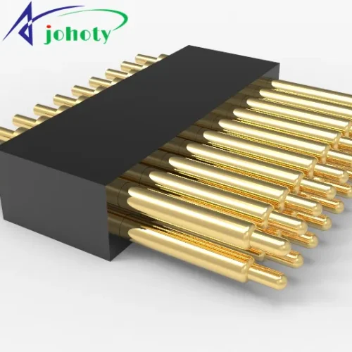
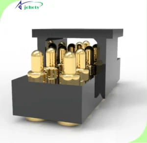
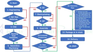
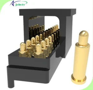
7. Production Process from Pogo Pins to Pogo Pin Connectors.
In general, a pogo pin connector contains one or more spring loaded pins and a housing.
Pogo Pin Assemble Process.
Including plunger alignment, spring alignment, barrel alignment, and assembly. Barrel entrance riveting, and rebound testing of pogo pin. At the time, a complete pogo pin is ready.
Pogo Pin Connector Production Process.
Alignment of pogo pins and housing. Load pogo pins into housings. Riveting each sub-parts to finished connectors.
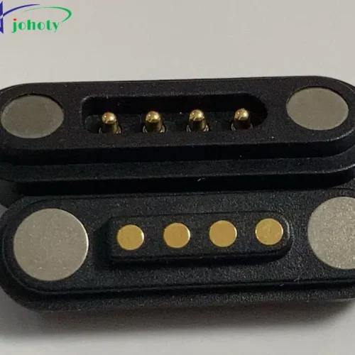
8. Design a Magnetic Connector Based on Spring Loaded Pin.
For magnetic connector, is unsuitable for SMT due to high temperature. Avoids direct exposure to avoid test failure during salt spray test, hand sweat test, and impact cracking.
A strong magnetic force can interfere with other components (e.g. GPS chips, magnetic strips on bank cards, etc.), which we always avoid during the design.
Magnetic force always adsorbs other metal components and causes short circuits of the connector, our solution is to stick Mylar on the magnet surface.
Appropriate magnetic force: above 0.5kgf is recommended for smart wearable devices, and above 1.0kgf is recommended for other magnetic connectors.
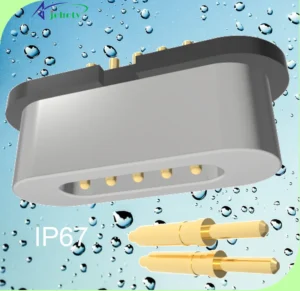
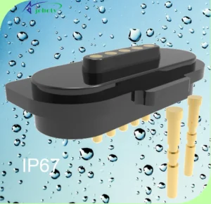
9. How To Realize Spring Loaded Pin to Waterproof Connector?
Getting a waterproof connector, there are at least 4 technology solutions. It is upgraded based on a common Pogo pin connector. The top waterproof level is IP68 we can achieve, most are IP67, IP66, IP65, and so on.
Glue.
It has good waterproof performance. Applicable to all kinds of environments. For small devices in shape, and suitable for light and thin devices. High feasibility of mass production. Widely applied in smartwatches, SOS bracelets, and smart bracelets.
Molding.
It has small sizes and thin plastic. Simple process after assembly. High structural strength. It is for bracelets and smartwatches. Etc.
O-ring.
It is reliable and waterproof. Applicable to all kinds of environments. Large-scale waterproofing equipment is widely used. Its pitch is large a bit of >3.00mm. It is for overall sealed waterproof, i.e. watches, cell phones, navigation devices, and so on.
Glass sintering.
It has very good air tightness, it is up to 1×10⁻⁹Pa.cm3/s. Applicable to complex environments, for example: high temperature and high pressure. It is hard to produce and high cost. It is commonly used in the military industries.
10. How Are Spring Loaded Pin Mounted?
SMT Pogo Pins.
It is to usually add a cap and pack it by T&R. Usually, pack SMT pogo pins in T&R horizontally or vertically. SMT machines will automatically mount them onto PCB soldering pads. And, the radius of the soldering pad is more 0.20~0.50mm than the bottom diameter.
DIP Pogo Pins.
Its package is the same as SMT pogo pins, both are packed in T&R after adding a cap. But the difference is that DIP pogo pins are mounted in through-holes in PCB. SMT pogo pins are on the surface soldering pads. And, the radius of the inner hole is more 0.20~0.50mm than the tail pin diameter.
Double Ended Pogo Pins.
It is soldering free. Two plunger tips contact their corresponding contact points. How to fix them? You can mount them into your devices, the housing, sockets, or fixture first. And then, fix it on your devices. It is beautiful.
Bending Pogo Pins.
Pack them in T&R. SMT machine will automatically mount onto PCB. For those big-size bending pogo pins or pogo pin connectors. Customers also manually mount them on the PTH station. Pay more attention to the high temperature on the W/S station. Please contact us to confirm the considerations because there is about 265℃ on the W/S Station.
Right Angle Pogo Pins.
Also, pack them in T&R. and then mount them onto PCB like bending pogo pins. However, right-angle pogo pins are more flexible based on actual applications.
Solder Cup Pogo Pins.
It is an approach to contact a pogo pin with a PCB soldering pad by a wire. , It can also form male and female cables, male and male cables, USB cables, and so on.
Threaded Screw Pogo Pins.
It is a special method of connecting contact points by knob fastening.
Extending Plunger Pogo Pins.
It is a good high-current connector. You need to leave enough room for it to expand and contract at the end. Fix them by device, fixture, or housing.
IC Pogo Pins.
Like double-ended pogo pins, they also have a soldering fee. And directly mount in your housing, fixtures, sockets, or devices.
ICT Pogo Pins.
It is the simplest. It is okay to directly insert an ICT pogo pin into its receptacle. The plungers of ICT pogo pins contact test points on UUTs. And its tail pin contact instruments by the receptacle, and the wires on the receptacle.
11. How To Enhance Device Reliability With Spring Loaded Pin?
The pogo pins maintain a constant operating current and have a very low current of only 3 A. It operates at a voltage of mostly less than 12V, and they have a very stable spring force, which plays an important role in the connection. Compared to the same size of shrapnel connectors, pogo pins have greater stroke, as well as more stabilized contact.
And, pogo pins change relatively little when subjected to strong impacts from external forces. Based on the same compression stroke, pogo pins take up less space than a shrapnel connector. Pogo pins are compressed when their contact points don’t move. While the shrapnel connector will be relatively mobile position.
A stable contact point allows the device to obtain very stable electrical properties and better performance of the devices. Pogo pins have very long life cycles from 10,000 cycles to 100,000 cycles. This greatly enhances the reliability of devices.
12. How Do Pogo Pins Work?
Pogo pins are very flexible wires to conduct electronic signals or currents. Can quickly connect and disconnect. Will never affect the independence between two devices that pogo pins are connecting.
To conduct two independent contacts, we need to apply a certain amount of force The spring in the pogo pin plays this role. It will apply enough spring force to the plunger. It will better ensure stable contact between the pogo pin’s plunger and its corresponding contacts, ensuring conductivity.
So, the spring force of pogo pins varies depending on different products and applications. The tail pin of the Pogo pin is soldered to the PCB board. The current or electric signal is transferred from the inner wall of the barrel to another connected contact. Thus, accomplishing the transmission of the current or electric signal.
To increase the contact area between the inner wall of the barrel and the plunger. The end of the plunger is generally a beveled surface. So, the spring against the plunger when pressing down the plunger to the spring. Which will make a side of the plunger tightly next to the inner wall of the barrel.
13. How to Select an Appropriate Spring Loaded Pin?
Based on the actual applications of your devices and your requirements. We design the premium drawings that are finalized by you. The pogo pins can meet all specifications of the drawings, the pogo pins are the best then. 
14. What Is the Working Environment of Pogo Pins?
Temperature.
When the pogo pins are operating, the current generates heat at the contact points, resulting in a temperature rise. The operating temperature is equal to the sum of the ambient temperature and the temperature rise of the contacts. The limited temperature of our pogo pins is in the range of -65℃~+200℃, normal operating temperature is in the range of -40℃~+85℃.
Humidity.
High humidity will drop the insulation of the housing and corrosion of pogo pins. We always test under constant humidity and heat test conditions for a relative humidity of 90% ~ 95%. Temperature +40 ℃± 20℃, at least 96 hours.
Salt spray.
The pogo pins work in environments containing moisture and salts. Avoid possible galvanic corrosion of pogo pins, which may affect their physical and electrical properties. Salt spray time for most of our pogo pins is 48 hours.
Vibration and shock resistance.
They are important properties of pogo pins. It is an important indicator of checking the mechanical structure of the pogo pins. it is important in air and space, rail, and road transportation. And the reliability of the electrical contact. We often specify the peak acceleration, duration, and waveform of the shock pulse. As well as the time of the break during electrical continuity.
15. What Is the Life Cycle of Pogo Pins?
The life cycle of pogo pins can be up to 100,000 cycles, most are more than 10,000 cycles. One cycle is the process of pressing the plunger tip to the working height and back from the working height to the original position.
In the range of the life cycle, the values should not be more than their specification. Including contact resistance, isolation resistance, rating voltage, rating current, and spring force. Based on the life cycle, you will select the right contact pin quantity. At the same time, you need to think about the volume and spring force more.
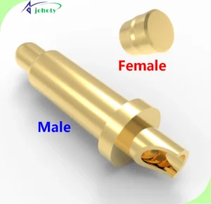
In some cases where high reliability is required and size permits, two contact pairs can be connected in parallel to improve the life cycles of the pogo pins. Male and female pogo pins or pogo pin connectors can generally be exchanged. We suggest that the female connectors or pogo pins are charged. Then, no one will touch the charged contacts.
It is more secure. Also, it can improve pogo pins’ life cycle. To maintain the life cycle, we need to pay attention to consider electrical continuity. During vibration, shock, and collision at specified frequencies and accelerations. 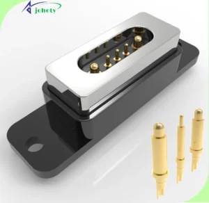
16. Test Items of Pogo Pins and Pogo Pin Connectors.
Electronical, including Contact Resistance Test and insulation Resistance. Dielectric Withstanding Voltage. Temperature Rise.
Mechanical, including Spring Force, Retention Force, and Durability. Mechanical Shock, Vibration. Sizes and dimensions.
Environmental, including temperature, humidity, Thermal Shock, and Temperature life cycles. Cold Resistance, Salt Spray, Solderability, Resistance to Solder Heat. As well as waterproof.
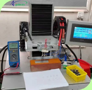
Testing and Inspection Equipment,
including Spring Force / Contact Resistance Tester. Network Analyzer(6GHz/20GHz), Contact Resistance/Lifetime Tester. Profile Projector, 30X to 350X Measuring Microscope. Life Tester, Microscope, Micro-focus X-Ray Fluoroscopic Inspection Tester. Plating Thickness Tester. Vickers Hardness Tester. X-ray fluorescence spectrometer (RoHS).
AC Source. DC Electronic Load, DC Power Supply. High Current Test Machine. Programmable DC Power Supply, White Light Interferometers. Microscope, Thermal Shock Tester, Salt Spray Tester. Temperature & Humidity Chamber, Hot-Air Reflow Machine.
17. What Package Is Pogo Pins?
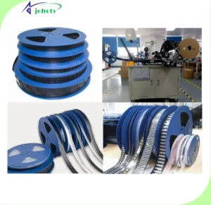
There are 5 common packages, including
PE bag, for small pogo pins, or small amounts of pogo pins.
T&R (tap and reel): for automatic SMT mounting, a cap is required to fix pogo pins or pogo pin connectors, then, the SMT machine is easy to pick up and put away.
Blister box/tray: for bending type pogo pins, or customized requirements,
Acrylic box: mainly for double ended IC pogo pins, or as per customer.
Pearl Foam: it is required to avoid any damage to products.
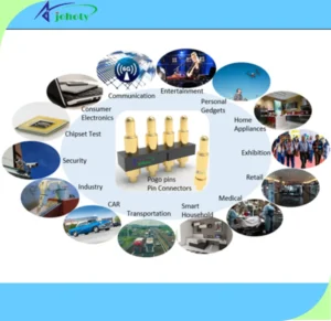
18. About Applications of Spring Loaded Pin!
Spring loaded pins are to build a communication bridge between blocked or isolated circuits within the circuit. Allowing the current to flow and enabling the circuit to perform its intended function. The application of pogo pins is very extensive.
Computers and computer peripherals:
including mainframe computers, minicomputers personal computers, and related equipment. Such as printers, modems, scanners, mass external storage devices, etc.
Data communications and telecommunications:
including data communications. Telephones, wireless radio television broadcasting equipment, etc.
Consumer electronic devices:
including Phones, PDAs, UAVs, televisions, VCRs, stereos, ARs, MRs, cameras, photographic apparatus, etc.
Automotive electrical and electronic devices:
automotive, cars, trucks, and other motor vehicles
Industrial electrical and electronic devices:
a wide range of pogo pins for use in strong electrical, hazardous environments, Such as aerospace, quick connectors for robots to hard metal shell connectors.
Ultimate!
We have described the pogo pins in detail in 18 ways. It should be the most professional and comprehensive introduction in the pogo pins industry. Each knowledge point comes from our R&D engineers and quality engineers. Process engineers, FAE engineers, and production managers.
They answered the questions asked by pretty many customers. We hope the foregoing is helpful to you, and if you have any further questions, please contact us.
[/ux_text]